
Circuit Diagram
Index 1403
BATTERY_CHARGING_CURRENT_LIMITER
Published:2009/6/19 2:50:00 Author:May
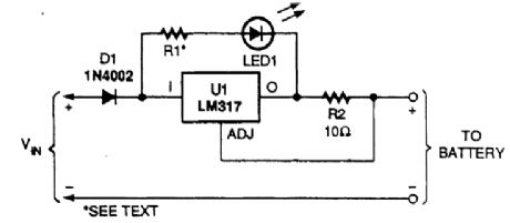
This circuit uses an LM317 as a current regulator to limit charging current to a lead-acid battery.R2 should produce a 1.2-V drop at the desired limiting value of charging current. (View)
View full Circuit Diagram | Comments | Reading(5358)
SIMPLE_LAMP_PULSER
Published:2009/6/19 2:50:00 Author:May
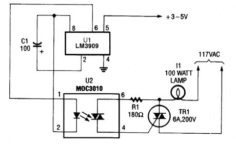
Here, the LM3090 (configured as a timing oscillator) is used to control a 117-Vac lamp through an MOC3010 optois olator/coupler. (View)
View full Circuit Diagram | Comments | Reading(2126)
SINGLE_CELL_LITHIUM_BATTERY_CHARGER
Published:2009/6/19 2:50:00 Author:May
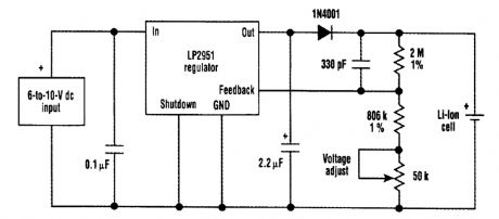
An LP2951 regulator was chosen for this single lithium cell-charging circuit for its built-in cur-rent-limiting capability. In addition, the regulator's output voltage is extremely stable, which is a pre-requisite for lithium battery charging. This figure details an example circuit designed to recharge a single cell. The required output set voltage was specified as 4.200 V (±0.025 V) with a maximum charging current of about 150 mA.An LP2951 regulator was selected for two reasons. One is that its built-in current limiter holds the maximum current to 160 mA (typical). The other is because the output voltage can be very ac-curately set to 4.200 V, thanks to the regulator's stable internal bandgap reference.The 1.23-V reference appears between the feedback pin and ground, which causes a precise current to flow in the output resistive-divider string. The amount of current flowing in these resis-tors determines (sets) the charger output voltage that appears across the battery terminals. Large-value resistors keep the battery drain below 2μA when the dc input is removed (a customer requirement). A trimming potentiometer sets the output to 4.200 V. It must be adjusted when the battery isn't connected to the charger output. A blocking diode is required at the LP295l's output to prevent current from flowing out of the battery and back into the output when the dc-input source is removed. Because the diode is in series with the output, the minimum input-output voltage dif-ferential required for this circuit to operate is about 1.5 V. (View)
View full Circuit Diagram | Comments | Reading(1640)
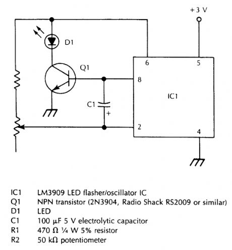
LED_PULSER_WITH_AUDIBLE_OUTPUT
Published:2009/6/19 2:49:00 Author:May
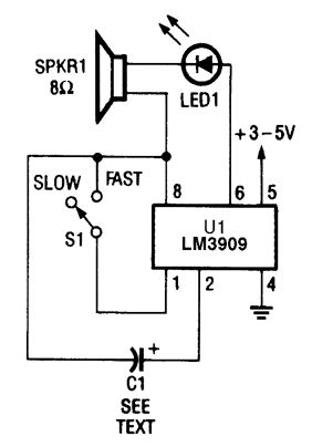
The LM3090 can also be used to drive both an LED and a speaker. In this circuit, each time that LED1 blinks, SPKR1 (an 8-Ω speaker) emits a sharp click sound. (View)
View full Circuit Diagram | Comments | Reading(1135)
LED_PULSER
Published:2009/6/19 2:48:00 Author:May
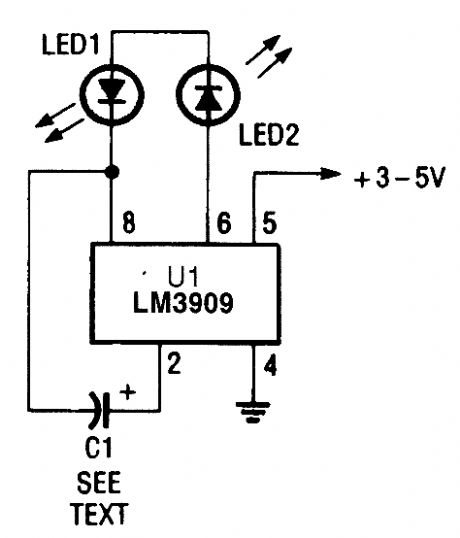
In this circuit, the LM3909 is used to drive a pair of series-connected LEDs. (View)
View full Circuit Diagram | Comments | Reading(2589)
BATTERY_CHARGER_CONTROLLER
Published:2009/6/19 2:47:00 Author:May
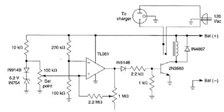
When the battery voltage is low, the TL081 comparator produces a high output, tuming on the 2N3569 relay driver. As the battery voltage approaches the set point, the relay driver is cut off, open-ing the 120-Vac supply. (View)
View full Circuit Diagram | Comments | Reading(2259)
VARIABLE_FREQUENCY_HIGH_POWER_LED_FLASHER
Published:2009/6/19 2:47:00 Author:May
View full Circuit Diagram | Comments | Reading(951)
RECHARGEABLE_LED_FLASHLIGHT
Published:2009/6/19 2:46:00 Author:May

This flashlight is useful for applications where night vision and/or darkness adaptation must be maintained. It uses an HLMP8150 T4 LED with a wavelength of 637 nm. This schematic is for the flashlight module. When the battery pack consisting of the four NiCad cells is fully charged (and there is no voltage at J1), 4.8 Vdc flows through trimmer potentiometer R2, the normally closed con-tact of relay RY1, and push-on/push-off power switch Al. Trimmer R2 limits the current flowing through LED1. Switch 51 can turn LED1 on and off when the battery is not being charged. (View)
View full Circuit Diagram | Comments | Reading(2373)
OPTICAL_ISOLATOR_WATTMETER
Published:2009/6/19 2:45:00 Author:May
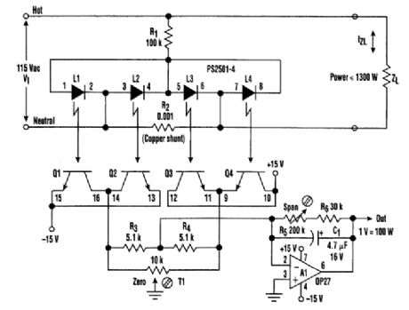
The quad-channel optical isolator, consisting of LED L1 through L4 and phototransistors Q1 through Q4, is connected in a double bridge configuration. The arrangement serves to compute the four-quadrant product of ac line voltage and 21 load current. The result is an accurate representa-tion of the true instantaneous power delivered to the load--even if the line voltage wanders and the load is reactive and nonlinear. This wattmeter function is, of course, optically isolated from the ac line, has full-scale limit of 1300 W, and is output with scale factor of 1 V/100 W. (View)
View full Circuit Diagram | Comments | Reading(2495)
SMART_BATTEY_CHARGER
Published:2009/6/19 2:45:00 Author:May
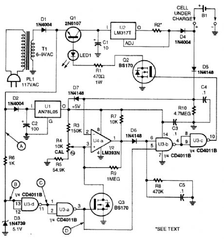
This charger will work with NiCad or the new rechargeable alkaline batteries. The Smartcharger is comprised mainly of four chips-an AN78L05 5-V, 100-mA regulator (U1), an LM317T 1-A adjustable-voltage regulator (U2), a CD4011BE quad 2-input NAND gate (U3), and an LN393N dualvoltage comparator (U4). The value and rating of R2 is selected as described irt the text. R2 is selected for a l.2-V drop across it at the charging current (3Ω for 400 mA, 6Ω for 200 mA). (View)
View full Circuit Diagram | Comments | Reading(2394)
DUAL_FLASHER_ADD_ON_FOR_555_CIRCUITS
Published:2009/6/19 2:44:00 Author:May

A pair of hex FETs drive two incandescent lamps in an altemating flasher circuit. The lamps can be 12-V automotive types, etc. (View)
View full Circuit Diagram | Comments | Reading(1033)
FLASHING_CHRISTMAS_LED_DISPLAY
Published:2009/6/19 2:43:00 Author:May
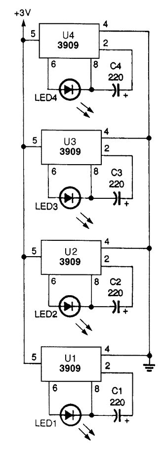
Using LEDs and 3909 ICs,you can make aflashing-light circuit that will run for months ontwo AA batteries. (View)
View full Circuit Diagram | Comments | Reading(797)
ANALOG_TACHOMETER_CIRCUIT
Published:2009/6/19 2:41:00 Author:May
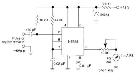
In this tachometer circuit a 555 is used as a pulse shaper. The dc value of the integrated pulse train is read by M1 which is calibrated to read frequency. With the values shown, the meter will read 0-1 kHz. (View)
View full Circuit Diagram | Comments | Reading(6031)
FLASHING_NEON_CHRISTMAS_LIGHTS
Published:2009/6/19 2:41:00 Author:May
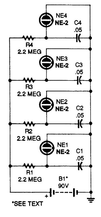
This flashing set of neon Christmas lights will make an attractive decoration for any time of year. B1 is made up of ten 9-V transistor radio batteries in series. The battery life can be measured in months. (View)
View full Circuit Diagram | Comments | Reading(980)
AUTOMOTIVE_HI_ZTEST_LIGHT
Published:2009/6/19 2:41:00 Author:May
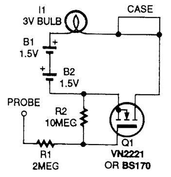
This test Iight has a high-input impedance and draws only 1 mA at 12V. Q1 switches dc to a battery and lamp circuit. (View)
View full Circuit Diagram | Comments | Reading(521)
ANALOG_TACHOMETER_CIRCUITS
Published:2009/6/19 2:41:00 Author:May
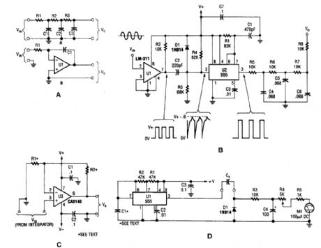
The four circuits shown are: a passive and active integrator, an analog tachometer, a scaling amplifier, and a capacitance meter. (View)
View full Circuit Diagram | Comments | Reading(1321)
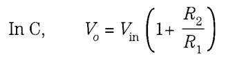
RANDOM_LED_STROBE
Published:2009/6/19 2:40:00 Author:May
This circuit generates a random output that is translated into LED movement by a prepro-grammed PIC16C55 microcontroller, U1. That PIC also senses and records the bias of the LED's movement. This device was originally used for an application involving psychokinesis testing where the person was asked to think the lights in either a clockwise or counterclockwise direction. (View)
View full Circuit Diagram | Comments | Reading(3117)
AUTO_BATTERY_ISOLATOR_CIRCUIT
Published:2009/6/19 2:39:00 Author:May
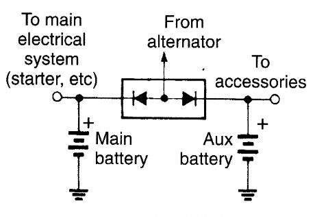
The diodes ensure that current can flow in both batteries from the altemator, but the main battery can't feed the accessory system, nor vice versa. (View)
View full Circuit Diagram | Comments | Reading(938)
SYN_COMBINER
Published:2009/6/19 2:38:00 Author:May
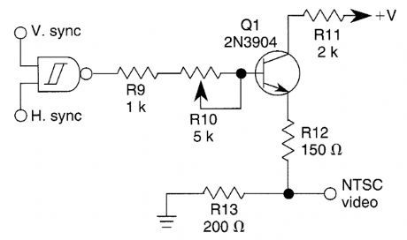
This circuit combines H and V sync signals at TTL or CMOS levels and produces an NTSC video sync output. (View)
View full Circuit Diagram | Comments | Reading(1840)
The subsonic remote control lamp switch circuit (2)
Published:2011/7/5 1:28:00 Author:zj | Keyword: The subsonic, remote control, lamp switch circuit
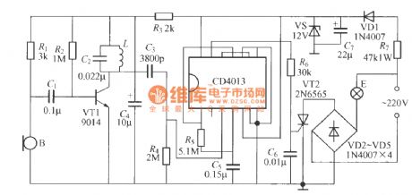
As shown in the figure ultrasonic remote control lamp switch circuit uses digital integrated circuit, which is composed of acoustic wave transducer, amplifier and general digital integrated circuit. In the graph, L is a 2.2mH inductance; 18kHz subsonic generator adopts a rubber ball puffer type ultrasonic horn. The acoustic transducer B can use CRZ2-113F ordinary electret capacitor microphone. (View)
View full Circuit Diagram | Comments | Reading(1257)
| Pages:1403/2234 At 2014011402140314041405140614071408140914101411141214131414141514161417141814191420Under 20 |
Circuit Categories
power supply circuit
Amplifier Circuit
Basic Circuit
LED and Light Circuit
Sensor Circuit
Signal Processing
Electrical Equipment Circuit
Control Circuit
Remote Control Circuit
A/D-D/A Converter Circuit
Audio Circuit
Measuring and Test Circuit
Communication Circuit
Computer-Related Circuit
555 Circuit
Automotive Circuit
Repairing Circuit