
Circuit Diagram
Index 1415
10_NOTE_SOUND_SYNTHESIZER
Published:2009/6/18 22:52:00 Author:May
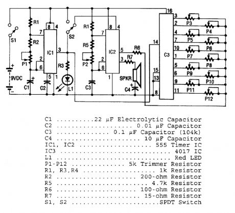
As shown, three ICs are used to produce the sounds. IC1 is a 555 timer that generates clock pulses. It is configured as an astable multivibrator. The frequency of the clock pulses is set by trim-mer potentiometer Pl. These clock pulses are coupled to the input of IC3 (a 4017 CMOS Johnson counter) on its clock input pin 14. Each clock pulse causes IC3 to shift a high to each of its output pins in sequence. A trimmer resistor, which can be adjusted to set a different frequency for each note, is connected to each of 103's output pins. One side of each of the trimmers is connected to pin 5 (the control voltage pin) of IC2.IC2, another 555 timer IC, creates the tone; the overall pitch of the tone can be varied by P2. As the output sequences from the 4017, that tone, which is changed in frequency by each output shift is applied to a srrtall speaker from pin 3 of IC2. An LED, which flashes with each clock pulse, is con-nected to pin 3 of IC1. Switch S2 is used to vary the sound between flowing and distinct notes. (View)
View full Circuit Diagram | Comments | Reading(1200)
SPACESHIP_ALARM
Published:2009/6/18 22:51:00 Author:May
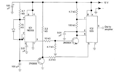
By using two 555 timers this circuit produces a low frequency tone that rises to a high frequency tone in a little over 1 second. Then the sound stops for about 0.3 seconds, thereafter the cycle re-peats. To produce the alarm sound of the Star Trek spaceship. (View)
View full Circuit Diagram | Comments | Reading(1033)
CRYSTAL_TUNED_AMPLIFIER
Published:2009/6/18 22:50:00 Author:May
View full Circuit Diagram | Comments | Reading(553)
BANDPASS_AMPLIFIER
Published:2009/6/18 22:38:00 Author:May
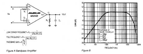
The circuit A is a bandpass amplifier,with the low corner frequency set by the impedance of the transconductance network,The high corner frequency IS set by the impedance ofthe RC network atthe amplifier output The passband gatn is (k)x (R1/RT). Figure B is a plot ofthe circuit in Figure A,with Rt=100Ω,Ct=20nF,R1=25Ω,and C1=395pF. (View)
View full Circuit Diagram | Comments | Reading(852)
TONE_CHIME
Published:2009/6/18 22:50:00 Author:May
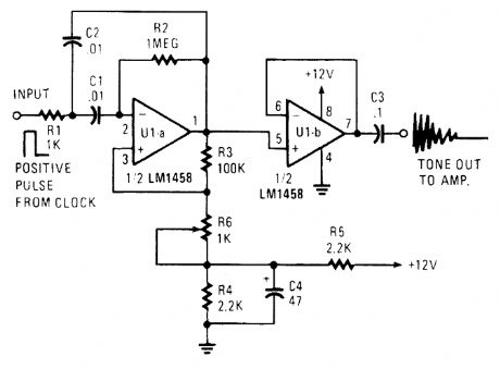
A positive pulse input to RI causes the active filter UI-a to ring. If the gain is set too high (R6), the circuit will oscillate. R6 controls the positive feedback and the Q of the circuit. C1 and C2 can be changed to adjust the tone frequency. (View)
View full Circuit Diagram | Comments | Reading(1137)
BASIC_LOGARITHMIC_AMPLIFIER_USING_OP_AMP
Published:2009/6/18 22:49:00 Author:May
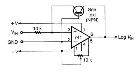
This logarithmic arnplifier uses a single op amp. The current in the feedback loop of the op amp ts equal to the current flow at the input of the op amp. (View)
View full Circuit Diagram | Comments | Reading(1317)
1000_Hz_PULSED_TONE_ALARM
Published:2009/6/18 22:48:00 Author:May
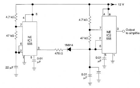
IC1 generates a pulse that modulates the 1000-Hz tone generated by IC2. This circuit can be used to generate warning or alert signals. (View)
View full Circuit Diagram | Comments | Reading(817)
SIREN_ALARM
Published:2009/6/18 22:48:00 Author:May
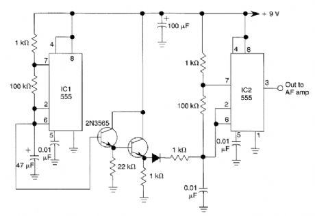
The ramp voltage from the low frequency oscillator IC1 modulates IC2 thereby producing a rising and falling tone like the siren wail of police cars. (View)
View full Circuit Diagram | Comments | Reading(992)
110_dB_BEEPER
Published:2009/6/18 22:45:00 Author:May
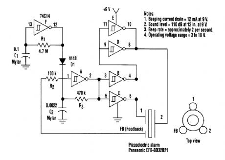
This circuit will gqnerate an ear-splitting 110 dB from 9 V. The setup uses a single 74C14 (CD40106B) CMOS hex inverting Schmitt-trigger IC, which must be used with a piezoelectric device with a feedback terminal. The feedback terminal is attached to a central region on the piezoelectric wafer. When the beeper is driven at resonance, the feedback signal peaks.One inverter of the 74C14 is wired as an astable oscillator. The frequency is chosen to be 5 times lower than the 3.2 kHz resonant frequency of the piezoelectric device. Feedback from the third pin of the beeper reinforces the correct drive frequency to ensure maximum sound output.Four other inverter sections of the IC are wired to form two separate drivers. The output of one section is cross-wired to the input of the second section. The differential drive signal that results produces about 18-V p-p when measured across the beeper. The last inverter section is wired as a second astable oscillator with a frequency of about 2 Hz. It gates the main oscillator on and off through a diode. For a continuous tone, the modulation circuit can be deleted. (View)
View full Circuit Diagram | Comments | Reading(1979)
CANARY_SOUND_SIMULATOR
Published:2009/6/18 22:42:00 Author:May
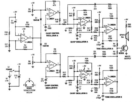
This circuit generates the sound of two canaries singing in a cage. Two LM324 quad amps make up seven oscillators. One os-cillator is an on/off control, the other six generate the sounds of two canaries. A 9-V supply powers the circuit. (View)
View full Circuit Diagram | Comments | Reading(1759)
ΔRATIO_COMPUTER
Published:2009/6/18 22:41:00 Author:May
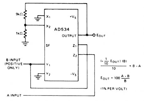
The percentage-deviation function is of practical value for many applications in measurement, testing, and control. For example, the output of this circuit might be applied to a pair of biased comparators to stimulate particular actions or displays, depending on whether the gain of a circuit under test were within limits, or deviating by a preset amount in either direction.The indicated scale factor, 1%/V, is convenient. However, other sensitivities, from 10%/V to 0.1%/V, as required by the application, can be obtained by altering the feedback attenuation ratio, from 1 to 1/100. Gain or attenuation is easily applied to the A signal externally for calibration to the normalized form. (View)
View full Circuit Diagram | Comments | Reading(512)
LOW_VOLTAGE_MICROPHONE_PREAMP
Published:2009/6/18 22:41:00 Author:May
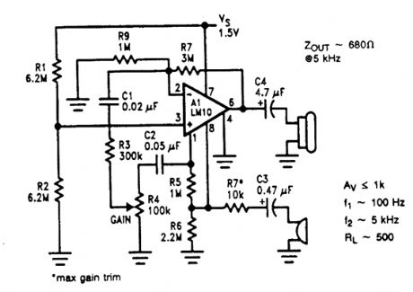
A microphone amplifier is shown. The refer-ence, with a 500-kHz unity-gain bandwidth, is used as a preamplifier with a gain of 100. Its out-put is fed through a gain-control potentiometer to the op amp, which is connected for a gain of 10. The combination gives a 60-dB gain with a 10-kHz bandwidth, unloaded, and 5 kHz loaded at 500Ω. Input impedance is 10 kΩ.Potentially, using the reference as a preampli-fier in this fashion can cause excess noise. How-ever, because the reference voltage is low, the noise contribution, which adds root-mean-square, is likewise low. The input noise voltage in this con-nection is 440-500 nV Hz, about equal to that of the op amp. (View)
View full Circuit Diagram | Comments | Reading(1103)
AUDIO_CONTROLLED_MAINS_SWITCH
Published:2009/6/18 22:40:00 Author:May
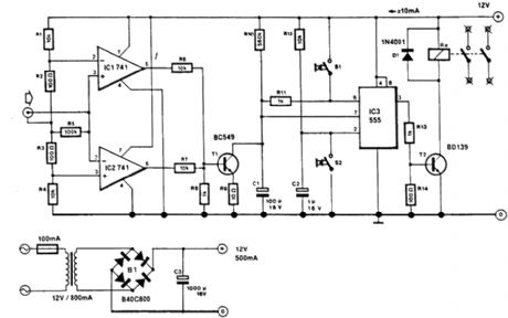
This circuit will switch off the line supply to audio or video equipment if there has been no input signal for about 2 seconds. S1 provides manual operation and S2 acts as a reset. This circuit allows for time to change a tape or compact disc. About 50 mV of audio signal is necessary. (View)
View full Circuit Diagram | Comments | Reading(739)
MOSFET_PUSH_PULL_AMPLIFIER
Published:2009/6/18 22:40:00 Author:May
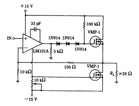
This amplifier can be used for audio or as a driver for inverter service. (View)
View full Circuit Diagram | Comments | Reading(1105)
HIGH_INPUT_IMPEDANCE_ac_AMPLIFIER
Published:2009/6/18 22:39:00 Author:May


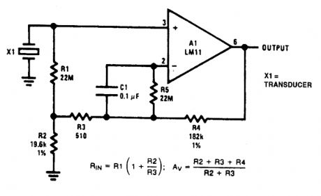
This figure shows an op amp used as an ac amplifier. It is unusual in that dc bootstrapping is used to obtain high input resistance without requiring high-value resistors. In theory, this increases the output offset because the op amp offset voltage is multiplied by the resistance boost.But when conventional resistor values are used, it is practical to include R5 to eliminate bias-current error. This gives less output offset than if a single, large resistor were used. C1 is included to reduce noise. (View)
View full Circuit Diagram | Comments | Reading(1293)
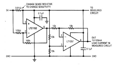
HIGH_SIDE_CURRENT_SENSING_AMPLIFIER
Published:2009/6/18 22:38:00 Author:May
View full Circuit Diagram | Comments | Reading(761)
SPEECH_SCRAMBLER
Published:2009/6/18 22:37:00 Author:May
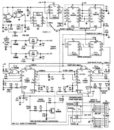
Using digital techniques, this circuit accomplishes the frequency-inversion algorithm via digiti-zation of the audio, inversion of the sign of every alternate sample, and D/A conversion of the resul-tant data. The result is an inverted frequency spectrum. Because the circuit has two channels, this system can be used in a full duplex two-way telephone scrambler.A complete kit ofparts is available from North Country Radio, PO. Box 53, Wykagyl Station, New Rochelle, NY 10804-0053A. (View)
View full Circuit Diagram | Comments | Reading(1244)
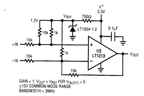
DIFFERENCE_AMPLIFIER_WITH_WIDE_INPUT_COMMON_MODE_RANGE
Published:2009/6/18 22:34:00 Author:May
View full Circuit Diagram | Comments | Reading(609)
TUNED_AMPLIFIER
Published:2009/6/18 22:33:00 Author:May
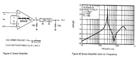
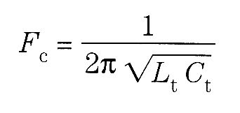
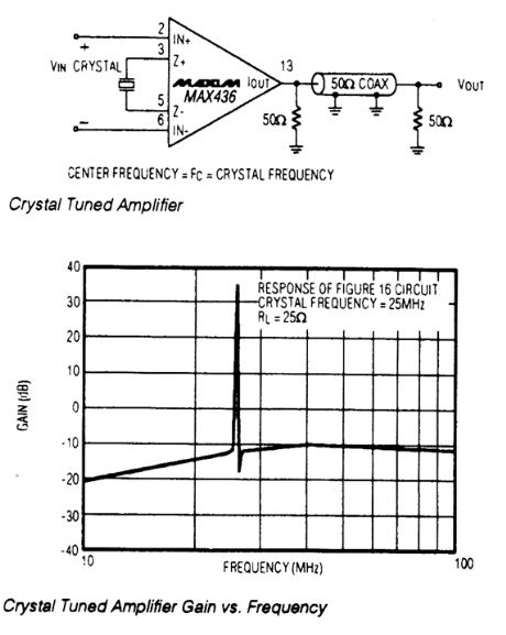
This circuit is a tuned amplifier circuit, tuned to the resonant frequency of the LC transconduc-tance network: The impedance of the transconductance network is a minimum at the resonant frequency, providing maximum amplifier gain at that frequency. The Q of the amplifier is a function of the parasitic components associated with the LO network. The graph is the frequency response of the circuit, with Lt=2.93 μH and Ct=9.9 pF. (View)
View full Circuit Diagram | Comments | Reading(1227)
AUDIO_CONTROLLED_SWITCH
Published:2009/6/18 22:32:00 Author:May
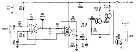
The audio-controlled switch combines a pair of 741 op amps, two 2N2222 general-purpose tran-sistors, a hexFET, and a few support components to a circuit that can be used to turn on a tape recorder, a transmitter, or just about anything that uses sound. (View)
View full Circuit Diagram | Comments | Reading(4)
| Pages:1415/2234 At 2014011402140314041405140614071408140914101411141214131414141514161417141814191420Under 20 |
Circuit Categories
power supply circuit
Amplifier Circuit
Basic Circuit
LED and Light Circuit
Sensor Circuit
Signal Processing
Electrical Equipment Circuit
Control Circuit
Remote Control Circuit
A/D-D/A Converter Circuit
Audio Circuit
Measuring and Test Circuit
Communication Circuit
Computer-Related Circuit
555 Circuit
Automotive Circuit
Repairing Circuit