
Circuit Diagram
Index 1408
WIDEBAND_VIDEO_SWITCH_FOR_RGB_SIGNALS
Published:2009/6/19 2:03:00 Author:May
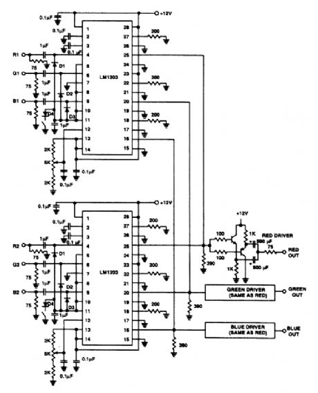
The switch shown selects 1to 2 inputs and uses a National LM1203. The slew rate is 4-V p-p into390 Ω in 5 to 7 ns. (View)
View full Circuit Diagram | Comments | Reading(745)
DIGITAL_BAROMETER
Published:2009/6/19 2:02:00 Author:May


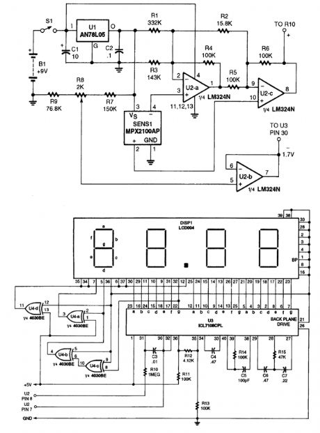
A pressure sensor is used in this application. This outputs a voltage to amplifier U2, and a 3 1/2 digit A/D converter module. It is calibrated to read barometric pressure in inches of mercury. (View)
View full Circuit Diagram | Comments | Reading(1021)
MINI_MEGAPHONE
Published:2009/6/19 2:02:00 Author:May
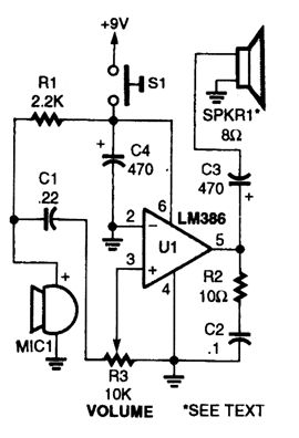
The Mini-Megaphone is comprised of an elec-tret microphone (MIC1), and LM386 low-voltage audio-power amplifier (U1), a horn speaker (SPKR1), and a few other components. (View)
View full Circuit Diagram | Comments | Reading(6)
SHORTWAVE_INTERFERENCE_TRAP
Published:2009/6/19 2:01:00 Author:May
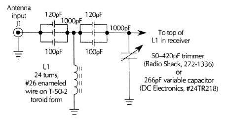
Build this interference trap to help block strong shortwave, broadcast, and FM stations from corning in on the shortwave bands. (View)
View full Circuit Diagram | Comments | Reading(971)
90_V_10_A_HIGH_POWER_AMPLIFIER
Published:2009/6/19 2:01:00 Author:May
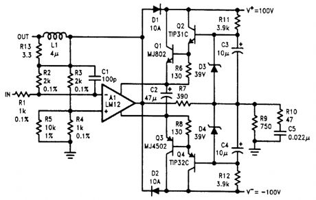
This amplifier can drive ±90 V at 10A, more than twice the output swing of the LM12. The IC provides current and power limiting for the discrete transistors. (View)
View full Circuit Diagram | Comments | Reading(2115)
AM_BROADCAST_TRAP_FOR_SIMPLE_SW_RECEIVERS
Published:2009/6/19 2:00:00 Author:May
View full Circuit Diagram | Comments | Reading(697)
dc_CONTROLLED_SWITCH_USING_OPTOISOLATOR
Published:2009/6/19 2:00:00 Author:May
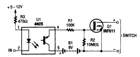
This dc-controlled switch uses an optoisola- tor/coupler, U1, to electrically isolate the input signal from the output-control device. (View)
View full Circuit Diagram | Comments | Reading(919)
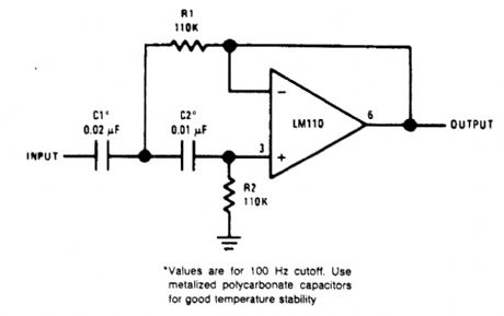
HIGH_PASS_ACTIVE_FILTER
Published:2009/6/19 1:59:00 Author:May
View full Circuit Diagram | Comments | Reading(1)
SIMPLE_VIDEO_AUDIO_SWITCHER
Published:2009/6/19 1:59:00 Author:May
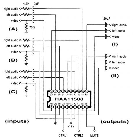
This channel selector selects video and stereo audio from any one ofthree different sources. The circuit should be constructed on a PC board with plenty of ground plane to minimize noise. (View)
View full Circuit Diagram | Comments | Reading(1872)
PIN_DIODE_FILTER_SELECTION_CIRCUIT
Published:2009/6/19 1:59:00 Author:May
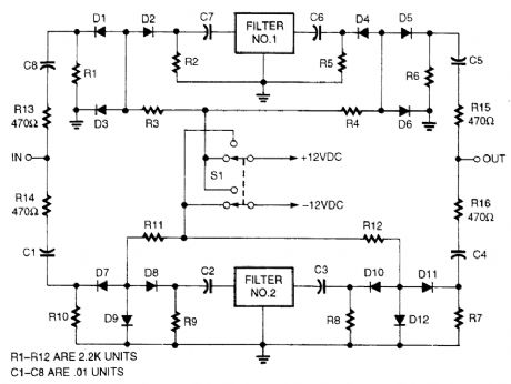
Selecting IF bandpass filters via series/shunt PIN-diode switching can be accomplished with this circuit. (View)
View full Circuit Diagram | Comments | Reading(913)
BRIDGE_CONNECTION_OF_TWO_POWER_op_AMPS
Published:2009/6/19 1:58:00 Author:May
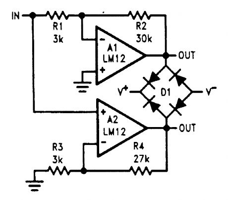
These bridge connections provide differential outputs that approach twice the total supply voltage. Diode bridge clarnps output to the supplies. (View)
View full Circuit Diagram | Comments | Reading(836)
GENERAL_PURPOSE_AF_AMPLIFIER
Published:2009/6/19 1:58:00 Author:May
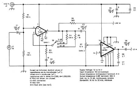
Schematic of the general-purpose AF amplifier.All resistors are 1/4-W,5%-tolerance carbon-com-position or metal-film units,Equivalent parts can be substituted,General purpose IC replacementsare shown in parentheses (View)
View full Circuit Diagram | Comments | Reading(673)
SHORTWAVE_RECEIVER_IF_FILTER
Published:2009/6/19 1:58:00 Author:May
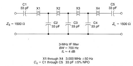
An inexpensive filter can be made from microprocessor crystals. This filter has 700 Hz BW (3 dB) and has a flat response (<1 dB) for about 400 to 500 Hz. Although a 3-MHz crystal was used, any frequency from 2 to 15 MHz (using fundamental crystal) should work, with appropriate scaling of components. Crystal resonant frequencies should match within 20% and preferably 10% of expected bandwidth (which is narrower as Cx increases. Impedance is reduced with wider bandwidths. (View)
View full Circuit Diagram | Comments | Reading(820)
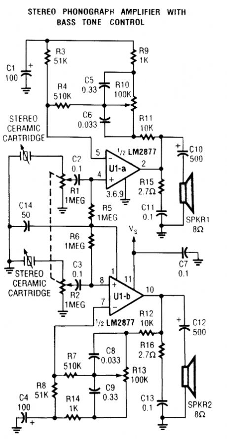
STEREO_PHONO_AMPLIFIER_WITH_BASS_TONE_CONTROL
Published:2009/6/19 1:57:00 Author:May
View full Circuit Diagram | Comments | Reading(719)
COMBINATION_FILTER
Published:2009/6/19 1:57:00 Author:May
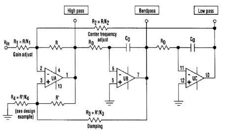
The classic state variable two-integrator filter is known for its insensitivity to component varia-tions, and its ability to provide three separate simultaneous outputs-low pass, high pass, and bandpass.Typically, a quad op amp is used to implement the state-variable filter. The classic configuration uses two integrating amplifiers, a filter input amplifier, and a filter feedback amplifier.The design described here combines both input and feedback amplifiers into one adder/subtrac-tor amplifier, achieving a three op-amp filter design (see the figure). (View)
View full Circuit Diagram | Comments | Reading(1843)
SECOND_ORDER_VOLTAGE_CONTROLLED_FILTER
Published:2009/6/19 1:55:00 Author:May
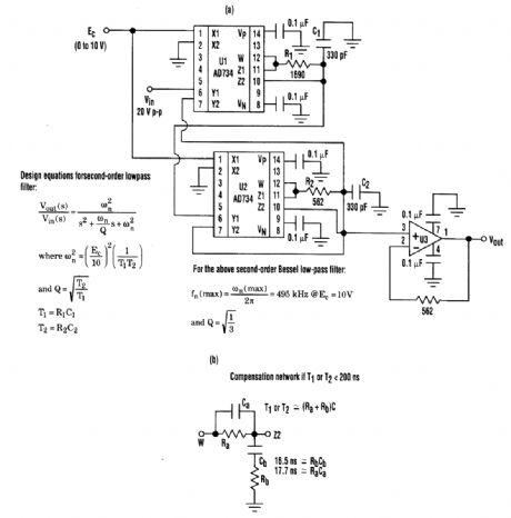
Desirable second-order voltage-controlled low-pass filter response can be achieved with this voltage-controlled filter (A). By using low-distortion, wide-bandwidth multipliers, it achieves higher cutoff frequencies than sv(itched-capacitor filters. If the circuit's RC network has a time constant less than 200 ns, it should be replaced by a lag compensator network (B). (View)
View full Circuit Diagram | Comments | Reading(771)
STEREO_PREAMPLIFIER
Published:2009/6/19 1:55:00 Author:May
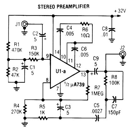
A building block for audio work, the circuit can be used as a general-purpose preamp. Use two circuits for stereo applications. (View)
View full Circuit Diagram | Comments | Reading(926)
MINUTE_MARKER
Published:2009/6/19 1:54:00 Author:May
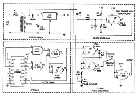
The figure shows the schematic of a minute marker. The output of transformer T1 is 12.6 Vac at 60 Hz, which is rectified by D1 and regulated by IC4, and LM7805 regulator, to provide 5 Vdc for the circuit. The unrectified ac is bandpass-filtered by R1, R2, R5, C1, and C2. Resistors R2 and R5 also form a dcvoltqge divider, which biases the input of Schmitt trigger IC3-a to 2.5 V. The Schrnitt trigger generates a 60-Hz square wave, which is fed to the input of IC1, a CE4040 12stage binary counter.The outputs of the counter are a 4081 quad AND gate (IC2), and the decoded output is fed back to the reset input of the counter, which resets the counter when the desired count is reached.The pulse from IC2-d is inverted by Schmitt trigger IC3-d, and passed along to the output pulse generator. The output pulse is generated by two Schmitt triggers cross-connected as an RS flip-flop (IC3-b and IC3-c). The output of the flip-flop is fed to 3, R4, and C3, whose values set the output pulse duration. The output pulse duration (T) can be approximated by the formula T=1.2×C3×(R3+ R4).A positive or negative-going pulse is selected by 51, and buffered by the remaining AND gate (IC2-a). (View)
View full Circuit Diagram | Comments | Reading(907)
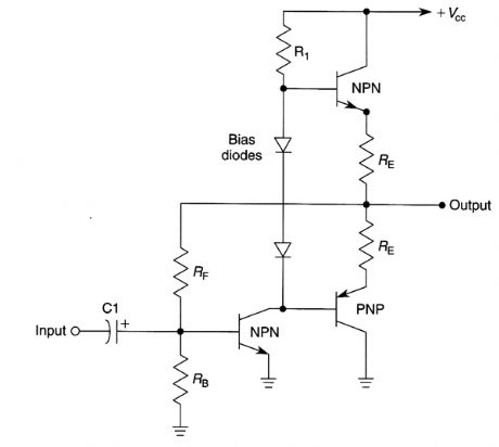
BASIC_COMPLEMENTARY_POWER_AMPLIFIER_CIRCUIT
Published:2009/6/19 1:54:00 Author:May
View full Circuit Diagram | Comments | Reading(689)
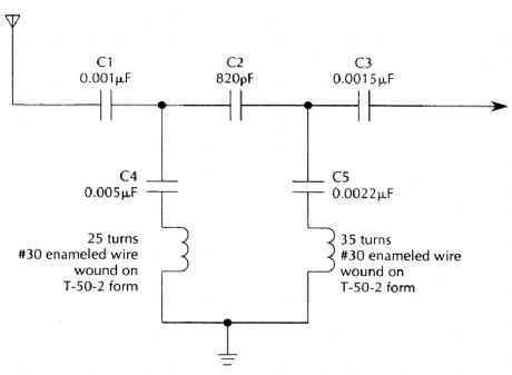
HIGH_PASS_FILTER
Published:2009/6/19 1:54:00 Author:May
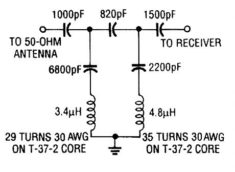
This high-pass filter will attenuate AM stations by 40 dB. Its low-frequency cutoff is about 2.2 MHz. This filter is useful for SW listening in areas of high AM radio signal strength. (View)
View full Circuit Diagram | Comments | Reading(1050)
| Pages:1408/2234 At 2014011402140314041405140614071408140914101411141214131414141514161417141814191420Under 20 |
Circuit Categories
power supply circuit
Amplifier Circuit
Basic Circuit
LED and Light Circuit
Sensor Circuit
Signal Processing
Electrical Equipment Circuit
Control Circuit
Remote Control Circuit
A/D-D/A Converter Circuit
Audio Circuit
Measuring and Test Circuit
Communication Circuit
Computer-Related Circuit
555 Circuit
Automotive Circuit
Repairing Circuit