
Circuit Diagram
Index 1410
ELF_MONITOR
Published:2009/6/19 1:42:00 Author:May
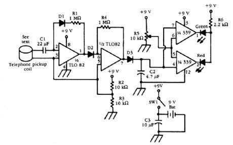
A telephone pick-up coil is used as a sensor for low-frequency magnetic fields. The signal is amplified and detected, then used to drive a comparator. (View)
View full Circuit Diagram | Comments | Reading(2699)
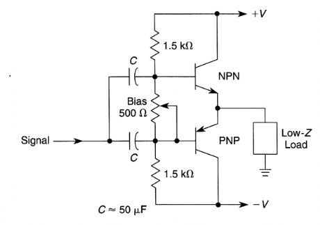
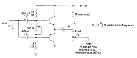
BASIC_COMPLEMENTARY_CLASS_AB_POWER_AMPLIFIER
Published:2009/6/19 1:41:00 Author:May
View full Circuit Diagram | Comments | Reading(756)
LINE_OPERATED_AUDIO_AMPLIFIER
Published:2009/6/19 1:41:00 Author:May
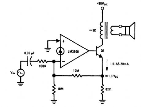
An audio amplifier which operates off a +98-Vdc power supply (the rectified line voltage) is of-ten used in consumer products. The external high-voltage transistor, Q1, is biased and controlled by the LM3900. The magnitude of the dc biasing voltage, which appears across the emitter resistor of Q1 is controlled by the resistor. The resistor is placed from the (-) input to ground. (View)
View full Circuit Diagram | Comments | Reading(811)
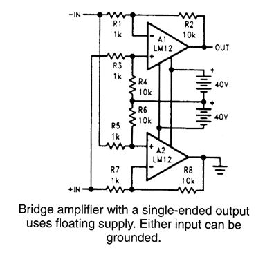
POWER_BRIDGE_AMPLIFIER_WITH_SINGLE_ENDED_OUTPUT
Published:2009/6/19 1:40:00 Author:May
View full Circuit Diagram | Comments | Reading(779)
10_WATT_AUDIO_AMPLIFIER
Published:2009/6/19 1:39:00 Author:May

This circuit is a general-purpose 10-W audio amplifier for moderate-power PA or modulator use in an AM transmitter. With higher voltages and a change in bias resistors, up to 30 W can be obtained. (View)
View full Circuit Diagram | Comments | Reading(1242)
FREQUENCY_BASED_LOCK
Published:2009/6/19 1:38:00 Author:May
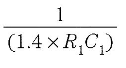

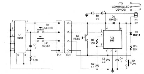


The system is formed by two separate circuits-a key and a keyhole. The key engages the key-hole with a mating pair of connectors. The key is a tone-generator circuit consisting of a 4049 hex in-verter CMOS IC (U1), switches (S1 and S2), a resistor (R1), and a capacitor (C1). The value of the tone generated by that circuit in Hz is determined by;The keyhole is a 567 tone-decoder circuit that can be conftgured to detect any frequency from 0.01 Hz to 500 kHz. The frequency it detects (fo), via the 567 IC, turns on the relay (K1). Compo-nents R3 and D1 are used to latch the circuit, so the output stays on even after the input tone is re-moved. When S2 is pressed, the system is reset. Switch S3 resets the circuit from inside. (View)
View full Circuit Diagram | Comments | Reading(991)
DMAl0 rectification module functional diagram
Published:2011/4/14 1:32:00 Author:muriel | Keyword: rectification module, functional diagram
View full Circuit Diagram | Comments | Reading(454)
PARALLEL_POWER_op_AMPS
Published:2009/6/19 1:37:00 Author:May
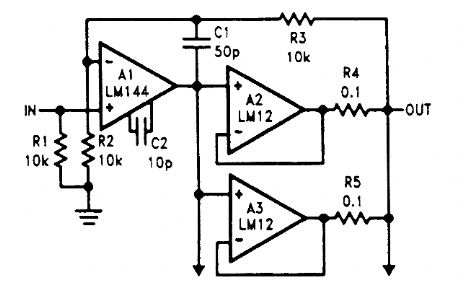
The power amplifiers, A2 and A3, are wired as followers and connected in parallel with the outputs coupled through equalization resistors. (View)
View full Circuit Diagram | Comments | Reading(1045)
CRYSTAL_CONTROLLED_FM_STEREO_TRANSMITTER
Published:2009/6/19 1:37:00 Author:May
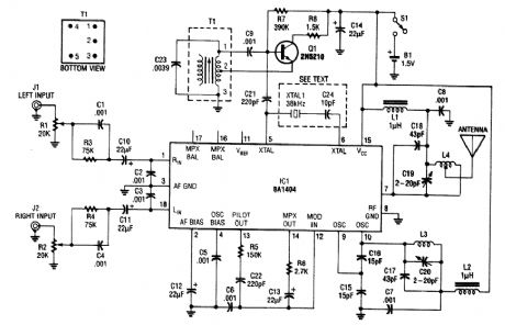
In this application, a BA1404 is used to generate an FM MPX baseband signal. This modulates a crystal oscillator (Q3) via a dual varactor series modulator. This transmitter can be to play CD audio on an existing FM auto radio. (View)
View full Circuit Diagram | Comments | Reading(2986)
ELECTRONIC_LOCK
Published:2009/6/19 1:36:00 Author:May
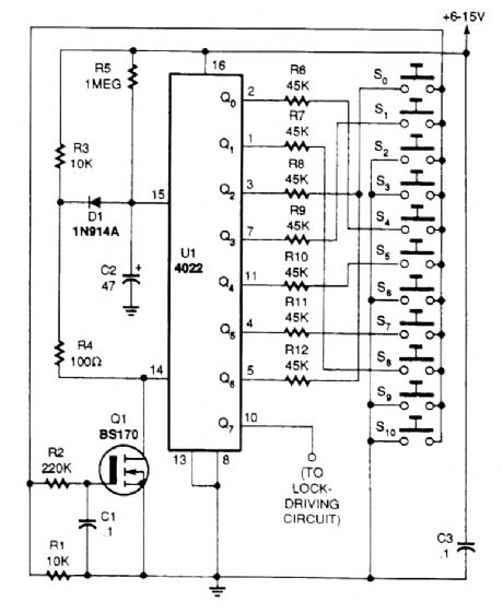
The heart of the circuit is a 4022 octal counter. When first powered up, C2 is charged via R5, so the reset input of the couitter is kept high. That causes output Qo to go high while all other outputs are low. With the switches wired as shown, when 54 is pressed, the BS170 is switched on via de-bouncing network R2/C1, and U1 receives a clock pulse. Also, C2 is discharged via R4 and D1 removing the reset signal of the counter, allowing it to advance. The time required for C2 to charge via R5 (e.g., to reset the counter), is the maximum time that can lapse before the next key is pressed.The above cycle is therefore repeated only if S8 (connected to the Q1 output) is pressed in time.When all keys have been pressed in time and in the correct order, Q7 goes high for about four sec-onds to drive the unlock circuitry (e.g., a relay driver for an automatic door opener. A builder can change the code by reviewing the switches. The code for the lock shown in the circuit diagram is 4-8-0-1-5-7-0. However, the 4022 octal counter can be replaced by a 4017 divide-by-10 counter. That will make it possible to add two more digits to the combination. (View)
View full Circuit Diagram | Comments | Reading(4)
DMAl2 Main schematic circuit diagram
Published:2011/4/24 22:28:00 Author:muriel | Keyword: schematic circuit diagram
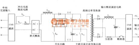
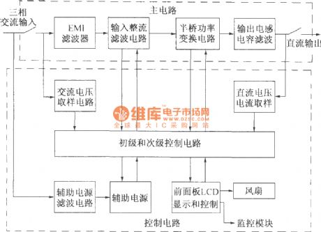
The figure shows a simplified schematic diagram of main circuit DMA12. It is mainly composed of input circuit and electromagnetic interference (EMI) filter circuit, impulse current limit circuit, the input rectifier filter circuit, the boost / power factor correction circuit and the absorption circuit, half-bridge power translation circuit, the output rectifier filter circuit. Compared with the DMA10, DMA12 uses single-phase input, boost/power factor correction method and lossless to absorb the buffer circuit, and the half-bridge DC / DC power conversion and output rectification filter part is the same with the DMA10.
(View)
View full Circuit Diagram | Comments | Reading(2042)
AUDIO_POWER_AMPLIFIER,15W,12V
Published:2009/6/19 Author:May
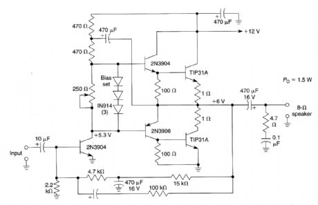
Although ICs have largely replaced circuits such as this, this circuit still finds use where the flexibil-ity of a discrete device design is desirable. Parts are easy to obtain and the problem of IC obsoles-cence is eliminated. The TIP31A can be heatsinked to a small metal heatsink, if desired. (View)
View full Circuit Diagram | Comments | Reading(1075)
AUDIO_FREQUENCΥ_METER
Published:2009/6/18 23:58:00 Author:May
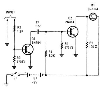
A pulse-shaper is used in a tachometer cir-cuit to drive a meter. (View)
View full Circuit Diagram | Comments | Reading(718)
FOUR_WIRE_RESISTANCE_MEASUREMENT_HOOkUP
Published:2009/6/18 23:57:00 Author:May
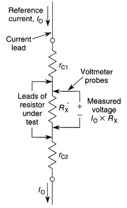
A true four-wire resistance measurement hookup. (View)
View full Circuit Diagram | Comments | Reading(709)
ELECTRONIC_EAR_LOW_NOISE_AUDIO_AMPLIFIER_FOR_PAROBOLIC_DISH_MIKES
Published:2009/6/18 23:57:00 Author:May

Use this circuit with a parabolic reflector microphone for eavesdropping on distant sounds. (View)
View full Circuit Diagram | Comments | Reading(1824)
THREE_TERMINAL_REGULATOR_CURRENT_SOURCE
Published:2009/6/18 23:56:00 Author:May
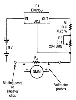
A three-terminal voltage regulator acts as a current source in this circuit. A resistor is being calibrated using a DMM and the current source. (View)
View full Circuit Diagram | Comments | Reading(823)
HIGH_IMPEDANCE_MICROPHONE_INPUT_CIRCUIT
Published:2009/6/18 23:56:00 Author:May
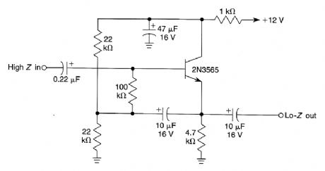
This input circuit will enable use of a high-impedance microphone where a low-impedance microphone would be needed. (View)
View full Circuit Diagram | Comments | Reading(1402)
BASIC_COMPLEMENTARY_CLASS_AB_SINGLE_SUPPLY_AMPLIFIER
Published:2009/6/18 23:56:00 Author:May
View full Circuit Diagram | Comments | Reading(682)
RIAA_PREAMPLIFIER
Published:2009/6/18 23:55:00 Author:May
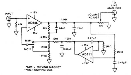
This preamp for RIAA phone use uses two op amps by Analog Devices. A switch selects compensation for moving magnet or rrtoving coil pickups. (View)
View full Circuit Diagram | Comments | Reading(2857)
POWER_SUPPLY_FOR_10_MHz_FREQUENCY_STANDARD
Published:2009/6/18 23:55:00 Author:May
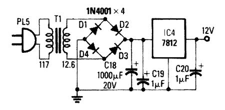
This simple power supply can be used in place of battery B1 of the 10-MHz frequency standard. (View)
View full Circuit Diagram | Comments | Reading(691)
| Pages:1410/2234 At 2014011402140314041405140614071408140914101411141214131414141514161417141814191420Under 20 |
Circuit Categories
power supply circuit
Amplifier Circuit
Basic Circuit
LED and Light Circuit
Sensor Circuit
Signal Processing
Electrical Equipment Circuit
Control Circuit
Remote Control Circuit
A/D-D/A Converter Circuit
Audio Circuit
Measuring and Test Circuit
Communication Circuit
Computer-Related Circuit
555 Circuit
Automotive Circuit
Repairing Circuit