
Circuit Diagram
Index 1419
STEREO_LINE_DRIVER
Published:2009/6/18 4:42:00 Author:May


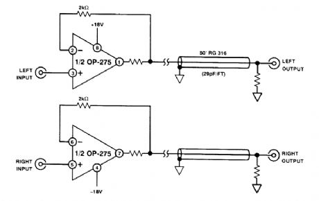
One Analog Devices OP-275 can be used for stereo line driver applications. (View)
View full Circuit Diagram | Comments | Reading(768)
SINGLE_PLATE_TOUCH_SENSOR
Published:2009/6/18 4:34:00 Author:May
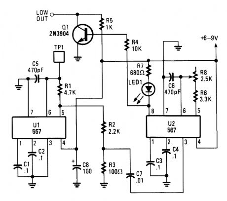
This system operates on the principle that capacitance loading of an oscillator will lower its fre-quency. When a foreign body comes into contact with touch plate, the frequency of U1 is lowered.This removes the oscillator signal from U1 from U2's passband, which causes U2 to lose lock, turns off the LED, and causes the colle,ctor of Q1 to go low. (View)
View full Circuit Diagram | Comments | Reading(1240)
TESTS_DRIVER_FOR_HOBBY_SERVOS
Published:2009/6/18 4:32:00 Author:May
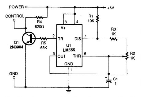
This circuit will generate the pulse used to control hobby servos. With the components shown the servo should produce a 90° total rotation. (View)
View full Circuit Diagram | Comments | Reading(945)
IMPEDANCE_MATCHED_LINE_DRIVER_WIHH_75_Ω_LOAD
Published:2009/6/18 4:31:00 Author:May
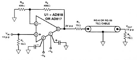
This circuit is a wideband 75-Ω line driver, for video applications (1 V p-p into 75Ω). (View)
View full Circuit Diagram | Comments | Reading(626)
MAST_MOUNTED_ATV_PREAMP
Published:2009/6/18 4:29:00 Author:May
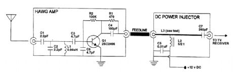
This simple ATV preamp covers the 427-to 439-MHz ATV frequencies and can be mast mounted and dc powered through the feedline. (View)
View full Circuit Diagram | Comments | Reading(1030)
TWO_INPUT_VIDEO_MUX_CABLE_DRIVER
Published:2009/6/18 4:29:00 Author:May

View full Circuit Diagram | Comments | Reading(660)
DUMMY_LOAD_AND_VIDEO_DETECTOR_FOR_TRANSMITTER_TESTS
Published:2009/6/18 4:29:00 Author:May
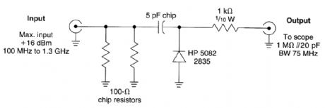
This circuit is useful as a video modulation monitor for testing low-power video transmitters. For higher power inputs, use a suitable attenuator between the detector and the source. The detector should be connected to scope with as short a cable as possible to preserve video bandwidth. (View)
View full Circuit Diagram | Comments | Reading(758)
LED_BARGRAPH_DRIVER_CIRCUIT
Published:2009/6/18 4:28:00 Author:May
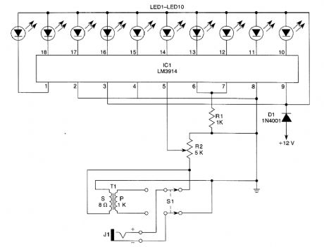
This circuit is used as an audio indicator. S1 selects direct input or a 1-kΩ(high impedance) audio input. R2 is a sensitivity control. (View)
View full Circuit Diagram | Comments | Reading(1038)
LCD_CONTRAST_TEMPERATURE_COMPENSATOR
Published:2009/6/18 4:26:00 Author:May
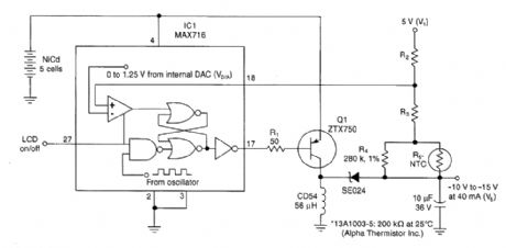
Negative temperature-coefficient resistor R5 modifies feedback in this switching regulator, which results in a negative output voltage that varies with temperature. With properly chosen resistor values, the circuit produces a temperature compensated bias voltage that ensures constant con-trast in an LCD. (View)
View full Circuit Diagram | Comments | Reading(1098)
VOICE_LEVEL_METER
Published:2009/6/18 4:24:00 Author:May
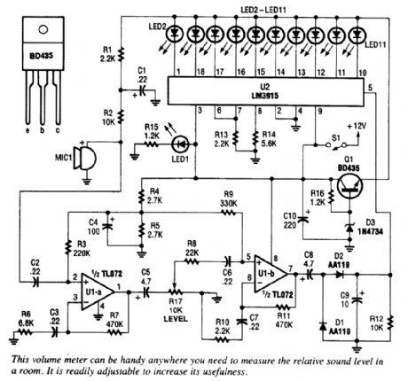
Using an LM3915 VU meter LED bar graph driver,10 LEDs are driven。A simple audio amplifierdrives a detector circuit,which provides dc drive for the LM3915. (View)
View full Circuit Diagram | Comments | Reading(6367)
LOW_COST_ACCURATE_SQUARE_ROOT_CIRCUIT
Published:2009/6/18 4:21:00 Author:May
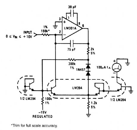

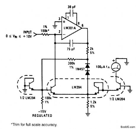
The circuit will generate a square-root function, accurately and inexpensiveJy. The output is a current that can be used to drive a meter directly or be converted to a voltage with a summing junc-tion current-to-voltage converter. The-15-V supply is used as a reference, so it must be stable. A 1% change in The-15-V supply will give a 1/2% shift in output reading. No positive supply is required when an LM301A is used because its inputs can be used at the same voltage as the positive supply (ground). The two 1N457 diodes and the 300-kΩ resistor are used to temperature-compensate the current through the diode-connected1/2 LM394. (View)
View full Circuit Diagram | Comments | Reading(1594)
SIMPLE_COLOR_ORGAN
Published:2009/6/18 4:21:00 Author:May
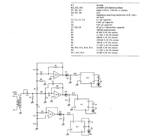
Three active filters that divide the audio spectrum into three bands drive rectifiers and then drive IC2, 3, and 4, flashing the LEDs at 6 Hz. D4, D5, and D6 should be three different colors for best effect. (View)
View full Circuit Diagram | Comments | Reading(1851)
BAR_GRAPH_LEVEL_GAUGE
Published:2009/6/18 4:20:00 Author:May
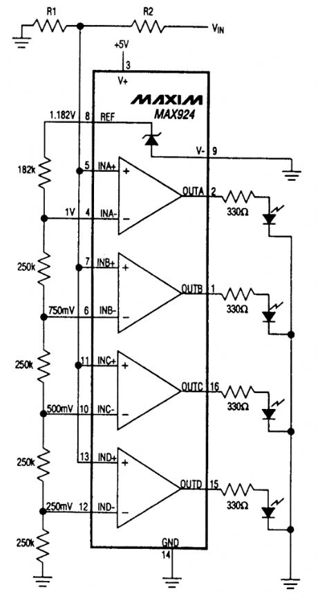
A quad comparator and divider network form a 4-level comparator that drives 4 LEDs. RI and R2 can be used to scale the basic sensitivity of 250 mV/LED to higher voltages than the basic 1 volt (for all 4 LEDs lit). (View)
View full Circuit Diagram | Comments | Reading(0)
HIGH_EFFICIENCY_DISPLAY_CONTRAST_AND_BACKLIGHT_CONTROL
Published:2009/6/18 4:19:00 Author:May

The LT1182 and LT1183 are compact high-performance solutions for powering LCD screens used in portable computers and instruments. Backlight control using a Cold Cathode Fluorescent lamp (CCFL) is accomplished with a switching regulator at efficiencies up to 90%. A second switch-ing regulator converts the positive input to either positive or negative bias voltages used for LCD contrast control. Both regulators allow full range of adjustment using a D/A converter, PWM or po-tentiometer control. Grounded bulb configurations are also easily controlled with minimal parts count. The 200-kHz switching frequency minimizes the size of transformers and external compo-nents. A shutdown mode powers down both regulators and reduces supply current to just 35 μA. (View)
View full Circuit Diagram | Comments | Reading(1312)
STEREO_LEVEL_DISPLAY
Published:2009/6/18 4:16:00 Author:May
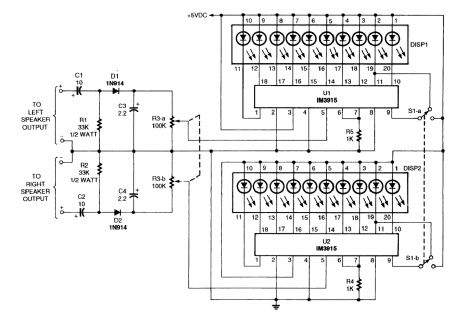
Two bar graph drivers and LEDs are used in this volume (level) indicator. R3a and R3b set the sensitivity of the circuit. The LEDs can be either bar graph units or individual LEDs can be used. (View)
View full Circuit Diagram | Comments | Reading(2554)
COLOR_SHIFTING_LED_DISPLAY
Published:2009/6/18 4:14:00 Author:May
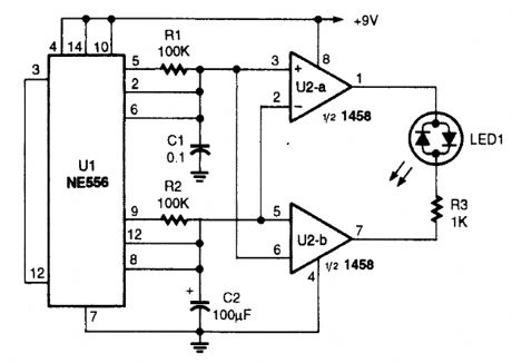
This circuit is used to make a tricolor LED gradually change color from yellow to red to yellow to green, and then back to yellow, where the cyclerepeats. It is very simple to make, and the theory of operation is also simple. Both of the timers in the556 dual oscillator/timer are configured for astable operation with a 50% duty cycle. 0ne timer is set uEDt to oscillate much faster than the other. The timing capacitor voltage of each is sent to two comparators, which apply a voltage across the tri-color LED whose polarity depends on which capacitor voltageis higher. The rapidly changing capacitor's voltage causes the red and green elements of the LED tobe altemately lit, thus giving the illusion of yeilow light. As the slowly rising and faLing voltage from the slower trimming capacitor changes in average value, it shifts the duty cycle to favor one color or the other. That gives the transition between colors a smooth appearance. (View)
View full Circuit Diagram | Comments | Reading(1931)
LATCHING_TOUCH_SWITCH_USING_CD4066B
Published:2009/6/18 4:13:00 Author:May
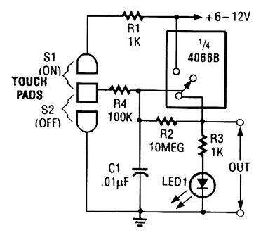
When touch switch S1 is activated, R4 is driven high, and the control voltage goes high, which latches the switch. When S2 is activated, R4 goes low and the control voltage goes low, which deactivates the switch. (View)
View full Circuit Diagram | Comments | Reading(935)
MULTIPLEXED_BCD_DECODER_DRIVER_CIRCUIT
Published:2009/6/18 4:12:00 Author:May
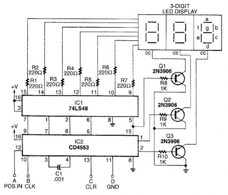
The BCD decoder-driver circuit will interface with any standard BCD output to produce a digital display. (View)
View full Circuit Diagram | Comments | Reading(2459)
TOUCH_ON_ONLY_SWITCH
Published:2009/6/18 4:11:00 Author:May
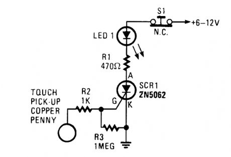
This touch on-only switch can be triggered into conduction by electrical means, and can only be reset by way of a mechanical switch. When the touch terminal is contacted by a finger, the SCR turns on and illuminates LED1. (View)
View full Circuit Diagram | Comments | Reading(863)
PRECISION_HIGH_GAIN_DIFFERENTIAL_AMP
Published:2009/6/18 4:10:00 Author:May
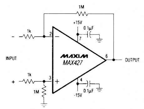
This circuit has a galn of 60 dB and a gatn bandwidth of 8 MHz. (View)
View full Circuit Diagram | Comments | Reading(688)
| Pages:1419/2234 At 2014011402140314041405140614071408140914101411141214131414141514161417141814191420Under 20 |
Circuit Categories
power supply circuit
Amplifier Circuit
Basic Circuit
LED and Light Circuit
Sensor Circuit
Signal Processing
Electrical Equipment Circuit
Control Circuit
Remote Control Circuit
A/D-D/A Converter Circuit
Audio Circuit
Measuring and Test Circuit
Communication Circuit
Computer-Related Circuit
555 Circuit
Automotive Circuit
Repairing Circuit