
Circuit Diagram
Index 287
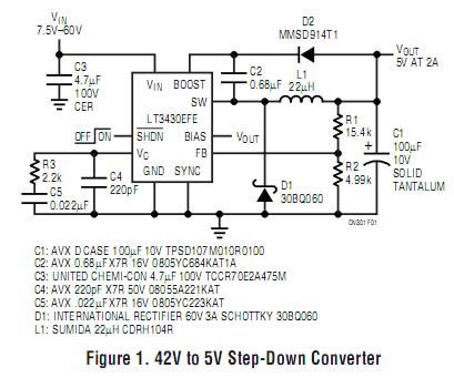
60V/3A Step-Down DC/DC Converter
Published:2012/10/29 22:06:00 Author:muriel | Keyword: 60V/3A, Step-Down DC/DC Converter
View full Circuit Diagram | Comments | Reading(4319)
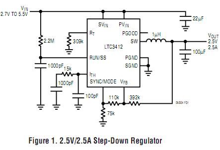
4MHz Monolithic Synchronous Step-Down Regulators
Published:2012/10/29 22:06:00 Author:muriel | Keyword: 4MHz, Monolithic Synchronous , Step-Down Regulators
View full Circuit Diagram | Comments | Reading(687)
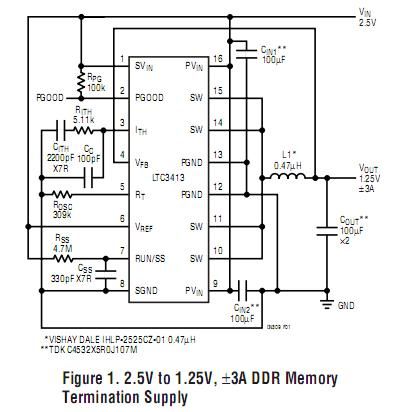
3A, 2MHz Monolithic Synchronous Step-Down Regulator
Published:2012/10/29 22:05:00 Author:muriel | Keyword: 3A, 2MHz, Monolithic Synchronous, Step-Down Regulator
View full Circuit Diagram | Comments | Reading(672)
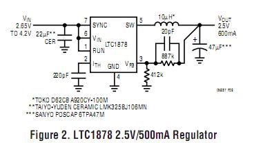
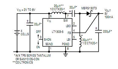
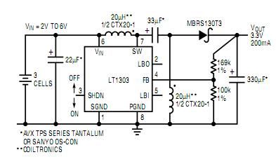
10µA Quiescent Current Step-Down Regulators
Published:2012/10/29 22:04:00 Author:muriel | Keyword: 10µA , Quiescent Current , Step-Down Regulators
View full Circuit Diagram | Comments | Reading(621)
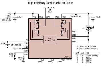
LTC3453 - Synchronous Buck-Boost High Power White LED Driver
Published:2012/10/29 22:03:00 Author:muriel | Keyword: LTC3453 , Synchronous Buck-Boost, High Power, White LED Driver
View full Circuit Diagram | Comments | Reading(1887)
Single Inductor, Tiny Buck-Boost Converter
Published:2012/10/29 22:03:00 Author:muriel | Keyword: Single Inductor, Tiny Buck-Boost Converter
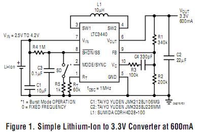
View full Circuit Diagram | Comments | Reading(1654)
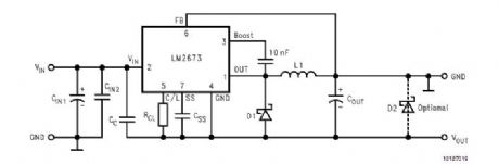
LM2673 Positive to Negative Converter
Published:2012/10/29 22:02:00 Author:muriel | Keyword: LM2673 , Positive to Negative Converter
View full Circuit Diagram | Comments | Reading(2271)
No Design Switiching Regulator
Published:2012/10/29 22:01:00 Author:muriel | Keyword: No Design Switiching Regulator
View full Circuit Diagram | Comments | Reading(705)
Micropower Buck/Boost Circuits, Part 2
Published:2012/10/29 22:00:00 Author:muriel | Keyword: Micropower Buck/Boost Circuits
View full Circuit Diagram | Comments | Reading(1053)
Micropower Buck/Boost Circuits
Published:2012/10/29 22:00:00 Author:muriel | Keyword: Micropower Buck/Boost Circuits
View full Circuit Diagram | Comments | Reading(1178)
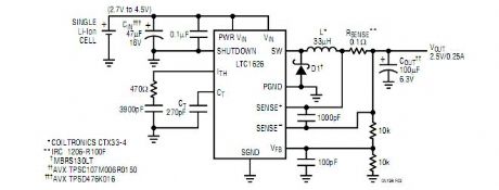
Single-Cell Li-Ion Battery to 2.5V Converter
Published:2012/10/29 21:59:00 Author:muriel | Keyword: Single-Cell, Li-Ion Battery , 2.5V Converter
View full Circuit Diagram | Comments | Reading(832)
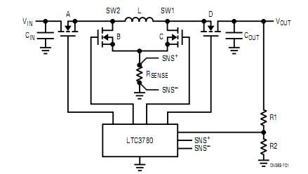
4-Switch Buck-Boost Converter
Published:2012/10/29 21:58:00 Author:muriel | Keyword: 4-Switch , Buck-Boost Converter
View full Circuit Diagram | Comments | Reading(2567)
Buck/Boost Charge-Pump Regulator Powers White LEDs from a Wide 1.6V to 5.5V Input
Published:2012/10/29 21:57:00 Author:muriel | Keyword: Buck/Boost, Charge-Pump Regulator, Powers White LEDs, Wide 1.6V to 5.5V Input
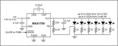
Since their invention a few years ago, white light-emitting-diodes (LEDs) have been steadily gaining in popularity. Because they offer whiter light and longer life than incandescent bulbs and are easier to use than fluorescent tubes, they have been steadily gaining market share in a variety of lighting applications, such as flashlights and display backlighting in handheld electronics. However, white LEDs present their own set of technical issues.An obvious issue for battery-powered equipment is the high forward voltage of white LEDs, which is typically 3.6V at 20mA and is usually specified as 3.0V minimum to 4.0V maximum. Once the voltage-drop of ballast resistors is added, the required bias voltage is even higher; therefore, typical battery systems require a voltage boosting DC-to-DC converter. Recently, several IC manufacturers have introduced various charge-pump and inductor-based boost converter ICs dedicated to driving white LEDs; however, at the time of this writing, none of these ICs support low-voltage operation from a two-cell stack of NiMH or alkaline batteries. Also, some of these dedicated ICs fail to regulate properly or even shutdown properly when presented with a 5V input, such as from a wall adapter. Although never intended for white LED bias applications, the MAX1759 buck/boost charge-pump is the first charge-pump to regulate white LEDs from a wide 1.6V to 5.5V input range. As implemented in the circuit of Figure 1, the MAX1759 will bias the LEDs with 15mA from inputs including two NiMH cells, two alkaline cells, three NiMH cells, three alkaline cells, a single Li+ cell, a regulated I/O voltage of 2.5V or 3.3V, a 5V wall adapter, or any combination of these for flexible systems. Unlike most charge-pumps, the IC incorporates a buck mode for proper regulation with 5V inputs, and internal circuitry fully disconnects the output in shutdown, eliminating LED leakage current and associated battery drain when off. Other features include PWM dimming via the active-low SHDN pin and fold-back current limiting for short-circuit protection. (View)
View full Circuit Diagram | Comments | Reading(829)
Buck Mode Switching Regulator for Solar Applications
Published:2012/10/29 21:56:00 Author:muriel | Keyword: Buck Mode, Switching Regulator , Solar Applications
View full Circuit Diagram | Comments | Reading(1327)
Voltage follower with 1G ohm input resistance
Published:2012/10/29 21:54:00 Author:muriel | Keyword: Voltage follower, 1G ohm input resistance
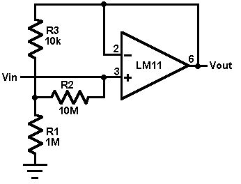
This circuit uses an LM11 to form a voltage follower with 1G ohm input resistance built using standard resistor values. With the input disconnected, the input offset voltage is multiplied by the same factor as R2; but the added error is small because the offset voltage of the LM11 is so low. When the input is connected to a source less than 1G ohm, this error is reduced. For an ac-coupled input a second 10M resistor could be connected in series with the inverting input to virtually eliminate bias current error; bypassing it would give minimal noise.
(View)
View full Circuit Diagram | Comments | Reading(937)
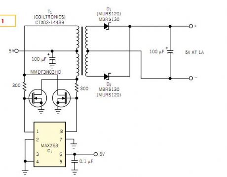
Push-pull driver provides isolated 5V at 1A
Published:2012/10/29 21:53:00 Author:muriel | Keyword: Push-pull driver , 5V , 1A
View full Circuit Diagram | Comments | Reading(2237)
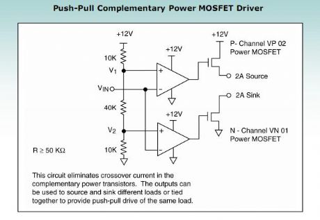
push-pull complementary power MOSFET driver
Published:2012/10/29 21:52:00 Author:muriel | Keyword: push-pull , complementary power , MOSFET driver
View full Circuit Diagram | Comments | Reading(2340)
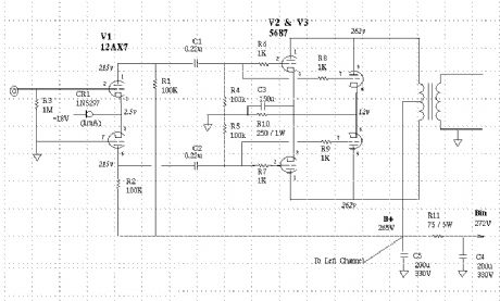
Push-Pull Class A Amp using type 5687 dual triodes
Published:2012/10/29 21:51:00 Author:muriel | Keyword: Push-Pull Class A Amp, 5687 dual triodes
View full Circuit Diagram | Comments | Reading(1533)
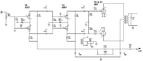
Push-Pull Class A 2A3 Stereo Amp
Published:2012/10/29 21:50:00 Author:muriel | Keyword: Push-Pull Class , A 2A3, Stereo Amp
View full Circuit Diagram | Comments | Reading(2204)
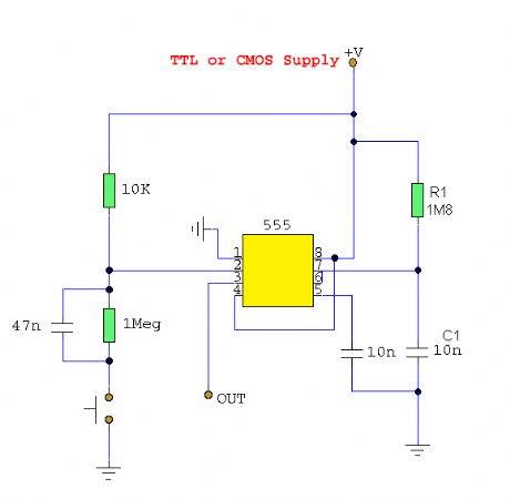
Switch De-Bouncer
Published:2012/10/29 21:49:00 Author:muriel | Keyword: Switch De-Bouncer
View full Circuit Diagram | Comments | Reading(919)
| Pages:287/2234 At 20281282283284285286287288289290291292293294295296297298299300Under 20 |
Circuit Categories
power supply circuit
Amplifier Circuit
Basic Circuit
LED and Light Circuit
Sensor Circuit
Signal Processing
Electrical Equipment Circuit
Control Circuit
Remote Control Circuit
A/D-D/A Converter Circuit
Audio Circuit
Measuring and Test Circuit
Communication Circuit
Computer-Related Circuit
555 Circuit
Automotive Circuit
Repairing Circuit