
Circuit Diagram
Index 293
BASS CONTROL
Published:2012/10/25 2:33:00 Author:muriel | Keyword: BASS CONTROL
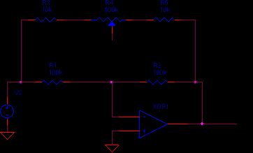
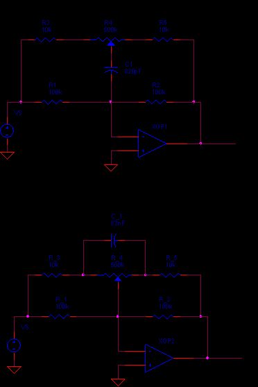
The bass control circuit induces some Deja Vu at first glance except for the position of one component - the capacitor. This time C1's mission is letting R3-R5 affect the gain at low frequencies, while leaving R1 and R2 alone at high frequencies. Based on your newly acquired treble control experience, understanding the bass control should be a snap. (View)
View full Circuit Diagram | Comments | Reading(1116)
TREBLE CONTROL
Published:2012/10/25 2:33:00 Author:muriel | Keyword: TREBLE CONTROL
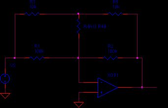
What should the frequency response of the treble circuit look like? Ideally, the gain should be flat at low frequencies. At higher frequencies, the gain can be cut or boosted by turning the control knob Clockwise (CW) or Counter-Clockwise (CCW). This amazing feat is accomplished via the simple inverting operational amplifier and several cleverly placed components.
The key to understanding its operation is to look at the low and high frequency extremes. First, at low frequencies, the capacitors open up leaving this circuit. (View)
View full Circuit Diagram | Comments | Reading(897)
Audio Tone Controls
Published:2012/10/25 2:32:00 Author:muriel | Keyword: Audio Tone Controls
Many people at one time or other, regardless of their interest in electronics, have adjusted these controls to suit their preference. Whether its to boost the bass of their favorite CD, cut the noise / static on a talk radio station or compensate for poor loud speaker response, they've reached for the treble and bass tone controls. The nice thing is that these circuits are straightforward to understand and implement. And the only difference between the treble and bass circuits is the location of a single capacitor. (View)
View full Circuit Diagram | Comments | Reading(938)
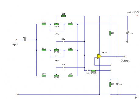
Tone Control
Published:2012/10/25 2:31:00 Author:muriel | Keyword: Tone Control
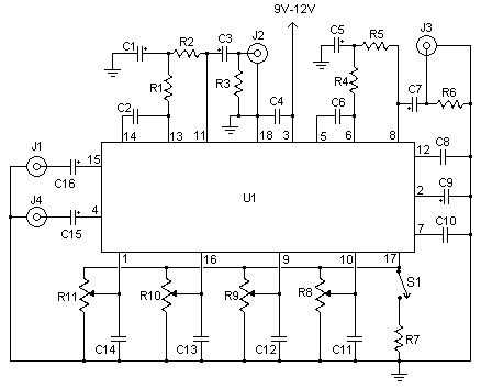
This simple tone control can be used in may audio applications. It can be added to amplifers, used as a stand alone control module, or even built into new and exciting instruments. It's one IC construction makes it a very compact circuit, as only a few support components are required. Plus, it does not use a dual power supply. This means that the circuit will run from 9V to 15V (although the bass will be a little weak at 9V). The circuit is by Robert Barg and originally appeared in the Think Tank column of the May 1998 issue of Popular Electronics. (View)
View full Circuit Diagram | Comments | Reading(0)
Audio Level Meter (vumeter) Circuit
Published:2012/10/25 2:30:00 Author:muriel | Keyword: Audio Level, Meter , vumeter Circuit
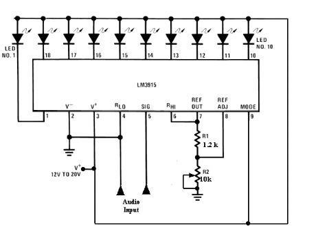
This circuit uses just one IC and a very few number of external components. It displays the audio level in terms of 10 LEDs. The input voltage can vary from 12V to 20V, but suggested voltage is 12V. The LM3915 is a monolithic integrated circuit that senses analog voltage levels and drives ten LEDs providing a logarithmic 3 dB/step analog display. LED current drive is regulated and programmable, eliminating the need for current limiting resistors. The IC contains an adjustable voltage reference and an accurate ten-step voltage divider. The high-impedance input buffer accepts signals down to ground and up to within 1.5V of the positive supply. Further, it needs no protection against inputs of ?35V. The input buffer drives 10 individual comparators referenced to the precision divider. Accuracy is typically better than 1 dB. (View)
View full Circuit Diagram | Comments | Reading(2227)
Audio levels meter
Published:2012/10/25 2:29:00 Author:muriel | Keyword: Audio levels meter
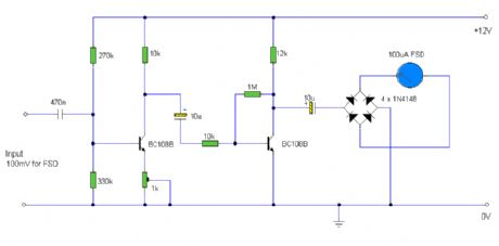
Audio levels can be monitored using a small panel meter with this circuit built from discrete components. (View)
View full Circuit Diagram | Comments | Reading(1053)
Audio Graphic Equaliser
Published:2012/10/25 2:28:00 Author:muriel | Keyword: Audio Graphic Equaliser

Audio graphic equalizers are very common as commercial products (for Hi-fi, car audio and stage use) but circuits for them are very rarely published. I didn't design this one but it's really very simple. The details shown are for a 7 band but the principle can be extended to almost any number of bands - if you can find accurate enough components. (View)
View full Circuit Diagram | Comments | Reading(1035)
Active Sub-Woofer and Controller
Published:2012/10/25 2:27:00 Author:muriel | Keyword: Active Sub-Woofer, Controller
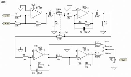
The controller is quite (actually very) simple, and the circuit is shown in Figure 1. An input buffer ensures that the input impedance of the source does not affect the integrator performance, and allows summing of left and right channels without any crosstalk. The output provides a phase reversal switch, so that the sub can be properly phased to the rest of the system. If the mid-bass disappears as you advance the level control, then the phase is wrong, so just switch to the opposite position. (View)
View full Circuit Diagram | Comments | Reading(2789)
Better Balance Control (Contributed by Bernd Ludwig)
Published:2012/10/25 2:27:00 Author:muriel | Keyword: Better Balance Control
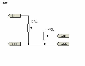
Bernd, a reader of The Audio Pages, has contributed a useful variation - in this case, a better balance control. Note that the configuration described requires a high impedance load, and the passive Better Volume Control cannot be used in this circuit. Used in the manner shown, it is a very similar concept to the better volume control of Figure 1, except it is (in a sense) the same idea in reverse.
Bear in mind that many (especially Japanese) designs use a specially designed pot for balance, and these are not suitable for the circuits shown below. These pots commonly have a centre detent, and the resistance of each track remains very low from the centre position to one end (or the other) of travel. These special pots are characterised by the level remaining constant in one channel or the other as the balance pot is moved. The overall law of these controls is (IMHO) unsatisfactory for hi-fi. (View)
View full Circuit Diagram | Comments | Reading(2526)
Better Volume Control (Pt. 2 - Further Ideas)
Published:2012/10/25 2:26:00 Author:muriel | Keyword: Volume Control
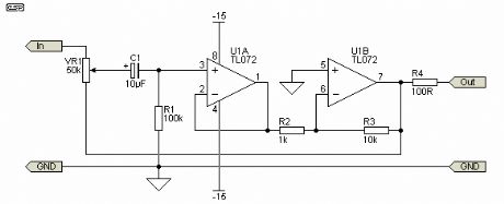
The input buffer enables the inverting stage (needed so the circuit can work) to have a very high input impedance. This would otherwise not be possible without the use of extremely high value resistors, which would increase the noise level considerably. The maximum gain as shown is 10 (20dB) and minimum gain is 0 (maximum attenuation). The input impedance is variable, and is dependent on the pot setting. At minimum gain, input impedance is the full 50k of the pot, falling to about 27k at 50% travel, and around 4k at maximum gain.
These impedance figures are very similar to the simple passive version (if a 100k pot is used), and again, a low impedance drive is required or the logarithmic law will not apply properly. The actual value for VR1 does not matter, and anything from 10k to 100k will work just as well, although it will influence the input impedance. The error at 50% of pot travel is less than 5% with values from 10k to 100k.
The additional benefit of improved tracking does not apply to the active version (at least not to the same extent), so use the best pot you can afford to ensure accurate channel balance. (View)
View full Circuit Diagram | Comments | Reading(1537)
Better Volume (and Balance) Controls
Published:2012/10/25 2:25:00 Author:muriel | Keyword: Better Volume, Balance Controls
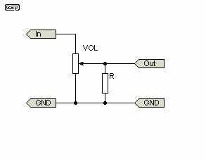
The volume control in a hi-fi amp or preamp (or any other audio device, for that matter), is a truly simple concept, right? Wrong. In order to get a smooth increase in level, the potentiometer (pot) must be logarithmic to match the non-linear characteristics of our hearing. A linear pot used for volume is quite unsatisfactory.
Unless you pay serious money, the standard log pot you buy from electronics shops is not log at all, but is comprised of two linear sections, each with a different resistance gradient. The theory is that between the two they will make a curve which is close enough to log (or audio) taper. As many will have found out, this is rarely the case, and a pronounced 'discontinuity' is often apparent as the control is rotated. (View)
View full Circuit Diagram | Comments | Reading(3176)
300W Subwoofer Power Amplifier
Published:2012/10/25 2:24:00 Author:muriel | Keyword: 300W , Subwoofer , Power Amplifier
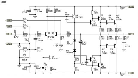
Please note that the specification for this amp has been upgraded, and it is now recommended for continuous high power into 4 Ohms, but You will need to go to extremes with the heatsink (fan cooling is highly recommended). It was originally intended for light intermittent duty, suitable for an equalised subwoofer system (for example using the ELF principle - see the Project Page for the info on this circuit). Where continuous high power is required, another 4 output transistors are recommended, wired in the same way as Q9, Q10, Q11 and Q12, and using 0.33 ohm emitter resistors.
Continuous power into 8 ohms is typically over 150W (250W for ±70V supplies), and it can be used without additional transistors at full power into an 8 ohm load all day, every day. The additional transistors are only needed if you want to do the same thing into 4 ohms at maximum supply voltage! Do not even think about using supplies over ±70V, and don't bother asking me if it is ok - it isn't!
The circuit is shown in Figure 1, and it is a reasonably conventional design. Connections are provided for the Internal SIM (published elsewhere on the Project Pages), and filtering is provided for RF protection (R1, C2). The input is via a 4.7uF bipolar cap, as this provides lots of capacitance in a small size. Because of the impedance, little or no degradation of sound will be apparent. A polyester cap may be used if you prefer - 1uF with the nominal 22k input impedance will give a -3dB frequency of 7.2Hz, which is quite low enough for any sub. (View)
View full Circuit Diagram | Comments | Reading(3108)
A 2 Watt audio amplifier
Published:2012/10/25 2:23:00 Author:muriel | Keyword: 2 Watt, audio amplifier
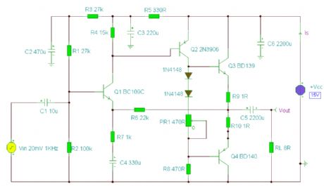
A 2 Watt audio amplifier made from discrete components. (View)
View full Circuit Diagram | Comments | Reading(1340)
A tone control circuit
Published:2012/10/25 2:22:00 Author:muriel | Keyword: tone control
A tone control circuit made with a single op-amp and having three ranges, bass, middle and treble controls. (View)
View full Circuit Diagram | Comments | Reading(2462)
Fan natural wind simulation and music accompaniment control circuit
Published:2012/10/24 22:30:00 Author:Ecco | Keyword: Fan , natural wind , simulation, music accompaniment , control
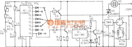
It is composed of relaxation oscillator, pulse counting frequency doubling circuit, SCR control socket circuit, music sound circuit and AC buck rectifier circuit and other components. When it issues the simulated natural wind, it is also accompanied by 12 international songs to give the joy of beauty. VT1 uses unijunction transistor BT33, and it forms form a relaxation oscillator with R1 ~ R3, C1, etc.
(View)
View full Circuit Diagram | Comments | Reading(1537)
The magnetic-sticker automatic speech billboard
Published:2012/10/24 22:36:00 Author:Ecco | Keyword: magnetic-sticker, automatic speech, billboard
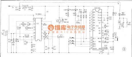
The automated automatic speech billboard is a magnetic automated voice ad playback device, and its decorative appearance is designed as a welcome cartoon which can be pasted in the lead black pole or advertising signs. When customer approached, it works automatically with welcomed arm swing and playing prerecorded slogan.
(View)
View full Circuit Diagram | Comments | Reading(5717)
The series inductance trimming tap speed adjusting circuit
Published:2012/10/24 22:52:00 Author:Ecco | Keyword: series , inductance , trimming, tap , speed adjusting
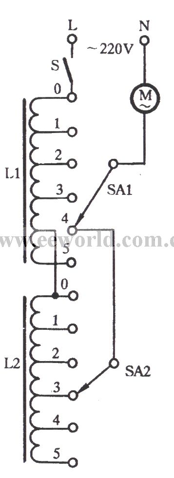
General ceiling fans is turned to fifth block ( end block ), but the speed is still faster with stronger wind. As shown in figure, the governor L1 is connected to a governor L2 in series to increase trimmable buck tap, then the fan can operate with breeze. L1 4 block tap wiring connections disconnect, then the connection is connected as shown in the figure. In this way, the first three gears can be adjusted by L1 governor; When Ll transferred to 4 gear, then SA2 is transferred to an appropriate gear, you can get the breeze.
(View)
View full Circuit Diagram | Comments | Reading(770)
Negative power supply circuit using TLC555
Published:2012/10/24 22:22:00 Author:Ecco | Keyword: Negative power supply

1B32 miniaturized package and high reliability index make it ideal for portable pressure detection system. Since 1B32 needs a negative supply, the Fig shows a practical circuit which can produce a negative voltage. It uses +12 V battery's positive pole to drive a CMOS TLC555 timer, and its typical supply current is 360μA. The timer outputs square wave to get 9V power after being rectified and filtered. 1B32 excitation voltage should be equal to or less than +9 V in order to stay out of regulating margin.
(View)
View full Circuit Diagram | Comments | Reading(1525)
Triac gas - smoke alarm circuit schematic
Published:2012/10/24 21:29:00 Author:Ecco | Keyword: Triac , gas - smoke alarm

In the event of combustible gas, the conductance of TGS308 gas sensor increases, and the voltage is removed through the potentiometer RP1 slide point, and its value is increased from normal 3V rms to 20V. This elevated voltage is added to transistor VT1 through diode and 4.7kΩ resistor, so that VT1 gets conduction, then Triacs 2N6070A gets conduction. Thus, the full-wave AC voltage drives H to produce up to 90dB alarm sound. H is Detal6003168 24V AC alarm. When gas disappears from the sensor, the circuit is restored to the original state, so the alarm automatically stops.
(View)
View full Circuit Diagram | Comments | Reading(1747)
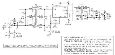
50 Ohm Long Line Receiver & Driver
Published:2012/10/24 1:20:00 Author:muriel | Keyword: 50 Ohm , Long Line, Receiver & Driver
View full Circuit Diagram | Comments | Reading(1500)
| Pages:293/2234 At 20281282283284285286287288289290291292293294295296297298299300Under 20 |
Circuit Categories
power supply circuit
Amplifier Circuit
Basic Circuit
LED and Light Circuit
Sensor Circuit
Signal Processing
Electrical Equipment Circuit
Control Circuit
Remote Control Circuit
A/D-D/A Converter Circuit
Audio Circuit
Measuring and Test Circuit
Communication Circuit
Computer-Related Circuit
555 Circuit
Automotive Circuit
Repairing Circuit