
Circuit Diagram
Index 286
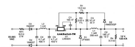
1.4 W Non-Isolated Buck Converter
Published:2012/10/30 21:45:00 Author:muriel | Keyword: 1.4 W , Non-Isolated, Buck Converter
View full Circuit Diagram | Comments | Reading(1949)
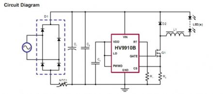
Buck-based LED Drivers Using the HV9910B
Published:2012/10/30 21:44:00 Author:muriel | Keyword: Buck-based LED Drivers, HV9910B
View full Circuit Diagram | Comments | Reading(2903)
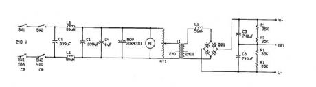
TESLA COIL DRIVER power supply
Published:2012/10/30 21:43:00 Author:muriel | Keyword: TESLA COIL DRIVER , power supply
View full Circuit Diagram | Comments | Reading(1302)
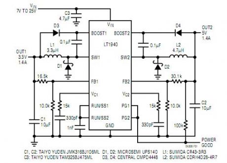
Dual Monolithic Buck Regulator
Published:2012/10/30 21:42:00 Author:muriel | Keyword: Dual Monolithic, Buck Regulator
View full Circuit Diagram | Comments | Reading(800)
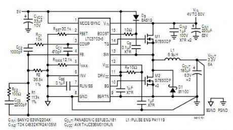
Rugged, Fast 60V Synchronous Controller
Published:2012/10/30 21:39:00 Author:muriel | Keyword: Rugged, Fast 60V , Synchronous Controller
View full Circuit Diagram | Comments | Reading(751)
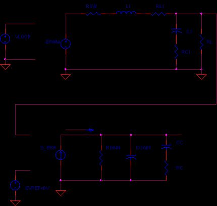
BUCK CONVERTER - AC MODEL
Published:2012/10/30 21:38:00 Author:muriel | Keyword: BUCK CONVERTER, AC MODEL
View full Circuit Diagram | Comments | Reading(991)
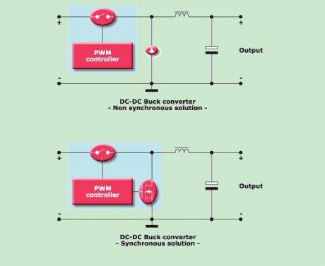
Buck Converter
Published:2012/10/30 21:30:00 Author:muriel | Keyword: Buck Converter
View full Circuit Diagram | Comments | Reading(983)
Synchronous buck MOSFET loss calculations
Published:2012/10/30 21:28:00 Author:muriel | Keyword: Synchronous buck MOSFET
View full Circuit Diagram | Comments | Reading(821)
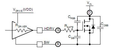
Typical Adaptive Gate drive
Published:2012/10/30 21:28:00 Author:muriel | Keyword: Typical Adaptive Gate drive

View full Circuit Diagram | Comments | Reading(710)
0 ~ 5V line graph indicator circuit with LM3914 series of point / line graph LED display driver integrated circuit
Published:2012/10/30 21:09:00 Author:Ecco | Keyword: 0 ~ 5V, line graph, indicator, series , point / line graph , LED display , driver integrated circuit
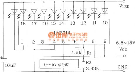
LM3914LED display driver IC is widely used. It uses external components and line changes to form a variety of display and alarm circuits, and cascade may constitute a multi- LED display.
(View)
View full Circuit Diagram | Comments | Reading(3733)
LED dispaly circuit with flashing alarm using LM3914 series of point / line graph LED display driver integrated circuit
Published:2012/10/30 21:11:00 Author:Ecco | Keyword: LED dispaly , flashing alarm , series, point / line graph , LED display , driver integrated circuit
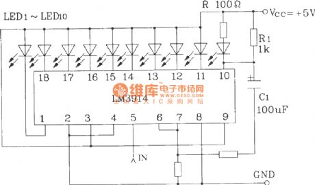
LED dispaly circuit with flashing alarm using LM3914 series of point / line graph LED display driver integrated circuit is shown as the figure.
(View)
View full Circuit Diagram | Comments | Reading(3418)
The LD7208 car turning alarm ASIC typical application circuit
Published:2012/10/30 21:15:00 Author:Ecco | Keyword: car turning alarm , ASIC, typical application
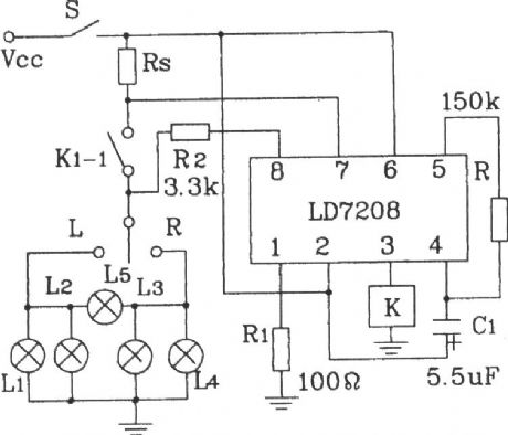
The main functions of the circuit: when operation is normal, the car light is intact, car light and bridge monitoring lamps flash at the same time, and the flashing frequency is 80 beats / min. Once the lights are damaged, the monitor lights flashing frequency will be doubled to show the alarm.
(View)
View full Circuit Diagram | Comments | Reading(1153)
Gas, gas detection alarm circuit using CH217 monolithic gas, gas detection alarm integrated circuit
Published:2012/10/30 21:24:00 Author:Ecco | Keyword: Gas, gas detection , alarm , monolithic gas, alarm integrated circuit
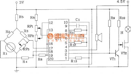
R1 in Figure is agas sensing probe, and its resistance reduces with a linear relationshipto gas concentration increasing, andRP3 is used to adjust the output ofamplifier, R6, R7 are used to draw forecasting and risk baseline signal voltages.
(View)
View full Circuit Diagram | Comments | Reading(1125)
The basic application circuit of BA6104 5-bit LED level meter driver integrated circuit
Published:2012/10/30 21:21:00 Author:Ecco | Keyword: basic application , 5-bit, LED level meter, driver integrated circuit
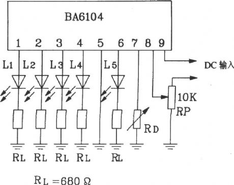
BA6104's input stage uses PNP composite transistor base electrode input mode, so input impedance is very high. The output stage uses emitter follower form, adjusting the external resistor RL in figure can change the LED driving current. Pin 7 is connected to a resistor to change Vref, when pin 7 is open, reference voltage Vref is controlled by the internal IC, and its value is approximately 1V.
(View)
View full Circuit Diagram | Comments | Reading(1825)
The oscillator and trigger circuit with operational amplifier
Published:2012/10/29 21:34:00 Author:Ecco | Keyword: oscillator , trigger , operational amplifier
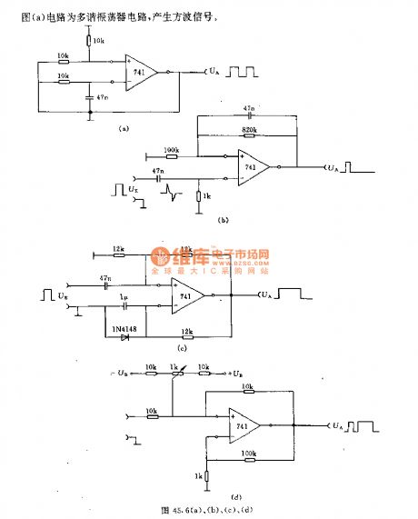
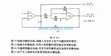
Fig a shows a multivibrator circuit which can generate square wave signal; Figure b is a flip-flop circuit which uses the under edge of the input signal to generate a trigger pulse signal. Figure c is a monostable circuit which can be used for waveform shaping or other signal conversion circuits. Figure d shows a Schmitt trigger circuit for waveform shaping or other signal conversion circuit. Figure e is a triangle wave and square-wave signal generator circuit.
(View)
View full Circuit Diagram | Comments | Reading(2114)
DC motor start circuit controlled by the time relay
Published:2012/10/29 21:50:00 Author:Ecco | Keyword: DC motor, start circuit, controlled , time relay
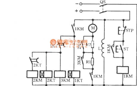
In fact, it is a resistor buck-start DC motor start circuit, but it uses time relay to control the shorted resistor. When the power switch QS is closed, pressing the start button ST can make the DC contactor 1KM be energized, the normally open contact is closed, then the armature loop is connected to R1 , R2. Time relay 1KT also starts at the same time, and its normally open contact 1KT is closed with a delay time, 3KM was energized to make R1 be shorted, then motor M accelerates.
(View)
View full Circuit Diagram | Comments | Reading(1501)
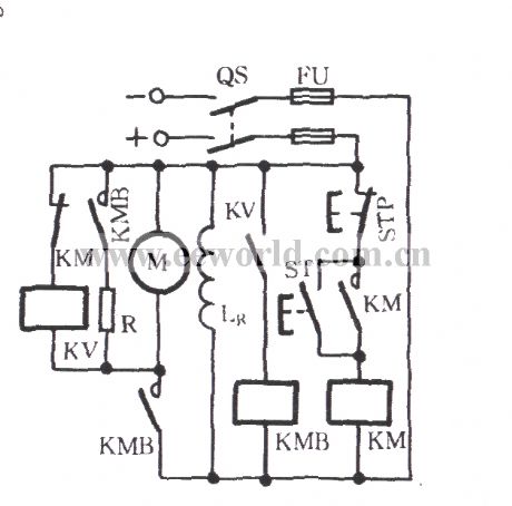
DC motor reverse brake circuit
Published:2012/10/29 22:10:00 Author:Ecco | Keyword: DC motor l reverse brake
No matter in DC motor and AC motor system, due to the inertia of rotor and its transmission parts, the entire transmission system can completely stop over a period of time after rotating motor power is cut off. However, in the production process, it is required to stop motor in order to improve work efficiency, and even called for an immediate stop, so the effective braking measures must be taken to the motor.
(View)
View full Circuit Diagram | Comments | Reading(1587)
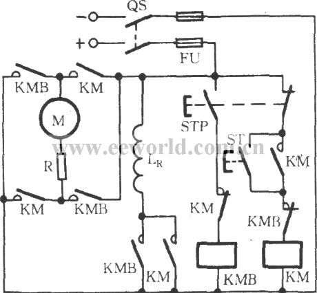
DC motor dynamic braking circuit
Published:2012/10/29 22:06:00 Author:Ecco | Keyword: DC motor l dynamic braking
When it is braking, pressing the stop button STP will make DC contactor KM be de-energized, the normally closed contact KM restores the closed state, so that the the voltage relay KV coil gets electric and moves, and its normally open contact KV is closed, then DC contactor KMB gets electric operation, the braking resistor R and armature M are connected in parallel. Excitation current direction has not changed, the torque generated by motor is the braking torque, so that the motor is rapidly stopped.
(View)
View full Circuit Diagram | Comments | Reading(2103)
DC motor servo control circuit
Published:2012/10/29 21:56:00 Author:Ecco | Keyword: DC motor , servo control
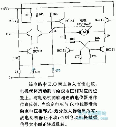
In the circuit, E, O points are input DC voltage, then the motor will be moved to a position corresponding to a given voltage. The potentiometer coaxially connected to motor is used as position feedback. When a given voltage and 1k potentiometer wiper contact voltage are equal, the differential amplifier output is zero, so the motor is stationary; Otherwise, the motor will be transferred or reversal according to the size of the signal.
(View)
View full Circuit Diagram | Comments | Reading(1632)
High Efficiency 500kHz, 4.5A Step-Down Converter
Published:2012/10/29 22:07:00 Author:muriel | Keyword: High Efficiency , 500kHz, 4.5A , Step-Down Converter
View full Circuit Diagram | Comments | Reading(875)
| Pages:286/2234 At 20281282283284285286287288289290291292293294295296297298299300Under 20 |
Circuit Categories
power supply circuit
Amplifier Circuit
Basic Circuit
LED and Light Circuit
Sensor Circuit
Signal Processing
Electrical Equipment Circuit
Control Circuit
Remote Control Circuit
A/D-D/A Converter Circuit
Audio Circuit
Measuring and Test Circuit
Communication Circuit
Computer-Related Circuit
555 Circuit
Automotive Circuit
Repairing Circuit