
Circuit Diagram
Index 299
Simple Adjustable Voltage Source
Published:2012/10/19 0:56:00 Author:muriel | Keyword: Simple, Adjustable, Voltage Source
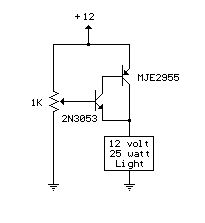
A simple but less efficient methode of controlling a DC voltage is to use a voltage divider and transistor emitter follower configuration. The figure below illustrates using a 1K pot to set the base voltage of a medium power NPN transistor. The collector of the NPN feeds the base of a larger PNP power transistor which supplies most of the current to the load. The output voltage will be about 0.7 volts below the voltage of the wiper of the 1K pot so the output can be adjusted from 0 to the full supply voltage minus 0.7 volts. Using two transistors provides a current gain of around 1000 or more so that only a couple milliamps of current is drawn from the voltage divider to supply a couple amps of current at the output. Note that this circuit is much less efficient than the 555 timer dimmer circuit using a variabe duty cycle switching approach. In the figure below, the 25 watt/ 12 volt lamp draws about 2 amps at 12 volts and 1 amp at 3 volts so that the power lost when the lamp is dim is around (12-3 volts * 1 amp) = 9 watts. A fairly large heat sink is required to prevent the PNP power transistor from overheating. The power consumed by the lamp will be only (3 volts * 1 amp) = 3 watts which gives us an efficiency factor of only 25% when the lamp is dimmed. The advantage of the circuit is simplicity, and also that it doesn't generate any RF interference as a switching regulator does. The circuit can be used as a voltage regulator if the input voltage remains constant, but it will not compensate for changes at the input as the LM317 does. (View)
View full Circuit Diagram | Comments | Reading(977)
2 Cell Lithium Ion Charger
Published:2012/10/19 0:56:00 Author:muriel | Keyword: 2 Cell, Lithium Ion Charger
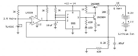
This circuit was build to charge a couple series Lithium cells (3.6 volts each, 1 Amp Hour capacity) installed in a portable transistor radio.
The charger operates by supplying a short current pulse through a series resistor and then monitoring the battery voltage to determine if another pulse is required. The current can be adjusted by changing the series resistor or adjusting the input voltage. When the battery is low, the current pulses are spaced close together so that a somewhat constant current is present. As the batteries reach full charge, the pulses are spaced farther apart and the full charge condition is indicated by the LED blinking at a slower rate.
A TL431, band gap voltage reference (2.5 volts) is used on pin 6 of the comparator so the comparator output will switch low, triggering the 555 timer when the voltage at pin 7 is less than 2.5 volts. The 555 output turns on the 2 transistors and the batteries charge for about 30 milliseconds. When the charge pulse ends, the battery voltage is measured and divided down by the combination 20K, 8.2K and 620 ohm resistors so when the battery voltage reaches 8.2 volts, the input at pin 7 of the comparator will rise slightly above 2.5 volts and the circuit will stop charging.
The circuit could be used to charge other types of batteries such as Ni-Cad, NiMh or lead acid, but the shut-off voltage will need to be adjusted by changing the 8.2K and 620 ohm resistors so that the input to the comparator remains at 2.5 volts when the terminal battery voltage is reached.
For example, to charge a 6 volt lead acid battery to a limit of 7 volts, the current through the 20K resistor will be (7-2.5)/ 20K = 225 microamps. This means the combination of the other 2 resistors (8.2K and 620) must be R=E/I = 2.5/ 225 uA = 11,111 ohms. But this is not a standard value, so you could use a 10K in series with a 1.1K, or some other values that total 11.11K
Be careful not to overcharge the batteries. I would recommend using a large capacitor in place of the battery to test the circuit and verify it shuts off at the correct voltage. (View)
View full Circuit Diagram | Comments | Reading(2646)
One or Two Cell Li-Ion Battery Charger
Published:2012/10/19 0:55:00 Author:muriel | Keyword: One or Two Cell, Li-Ion Battery Charger
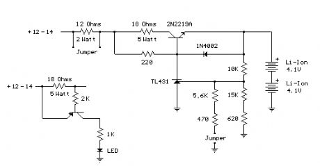
When the battery is low, the voltage at the reference pin of the TL431 will be less than 2.5 volts, causing the TL431 to switch off, increasing the transistor base voltage and charge current. Current is limited to around 300 mA by the 18 ohm resistor (2 cell setup). As the battery approaches full charge, the TL431 reference pin approaches 2.5 volts, increasing the TL431 current and reducing the transistor base voltage and charge current. Using 2 cells (8.2 volts, 1000 mAH), the current drops from 300mA to about 100mA as the charge reaches 75% of capacity in 200 minutes. Another hour is needed to bring the charge to 85% Note, the value of 4.1 rather than 4.2 was chosen for a little more margin, and less stress on the battery at full charge. From the data above, it looks like only 5% of capacity is lost. The diode prevents a reverse voltage across the e/b transistor junction in the event the power supply connections are shorted while the battery is still connected. The 220 ohm resistor was selected for about 20mA base current. The minimum transistor gain is 30, so 20mA should produce at least 600mA. The open circuit output voltage is set with a voltage divider for either 4.1 or 8.2 volts. Two jumpers are used to select the desired voltage and current limit.
For example, to charge a single Li-ion cell to 4.1 volts, the current through the 10K resistor will be (4.1-2.5)/ 10K = 160 microamps. The series combination of the other 2 resistors should total 2.5 / 160 uA = 15625 ohms. A 15K in series with 620 might be used, and the 620 adjusted to compensate for the 15K being slightly more or less. I ended up 15K and 750 since the 15K was a little low.
In the 2-cell (8.2 volt) case, two additional resistors are added in parallel with the 15625 (using the jumper) to increase the output voltage from 4.1 to 8.2. I ended up with 5.6K in series with 430 ohms. The 430 can be adjusted to get it just right.
A second jumper is used (across the 12 ohm resistor) to maintain approximately the same charge current with either single or double cell operation. Both jumpers are installed for 8.2 volt operation and removed for 4.1 volt operation. Note: The circuit board picture shows two 5 watt 12 ohm resistors. One of the resistors is out of tolerance and is actually 17 ohms.
Caution: Be careful not to set the jumpers for 8.2 volt operation while connected to a single cell (4.1 volt) battery. Use a DMM to verify the open circuit voltage is what you want before connecting the battery. (View)
View full Circuit Diagram | Comments | Reading(3624)
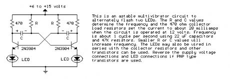
Astable Multivibrator
Published:2012/10/19 0:53:00 Author:muriel | Keyword: Astable Multivibrator
View full Circuit Diagram | Comments | Reading(0)
Telephone In-Use Relay Controller
Published:2012/10/19 0:52:00 Author:muriel | Keyword: Telephone, In-Use Relay, Controller

View full Circuit Diagram | Comments | Reading(693)
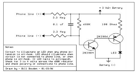
Telephone In-Use Indicator
Published:2012/10/19 0:52:00 Author:muriel | Keyword: Telephone In-Use, Indicator
View full Circuit Diagram | Comments | Reading(1101)
Do-it-yourself phone dialer security system
Published:2012/10/19 0:46:00 Author:muriel | Keyword: Do-it-yourself phone, dialer security system
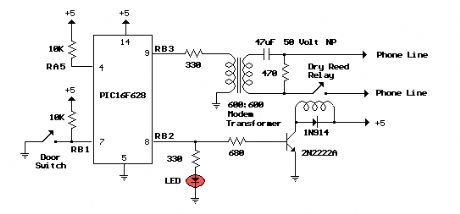
Do-it-yourself phone dialer security system calls your cell phone, office etc.whenever a door or window is opened, or panic button is pressed. Great Home Alarm.The circuit consists of a small PIC microcontroller, assembly program,and a few other parts to detect a switch closure from an open door, window,or manual push button and then dial the cell phone number, and transmit asteady tone to indicate the source of the call. The circuit uses the pulsedialing system to interrupt the line connection a number of times toindicate each digit. Pulse dialing (the oldest form of dialing) works byactually disconnecting or hanging up the phone line a number of timesto indicate each digit. For example, the digit 5 would be dialed bydisconnecting and reconnecting the line 5 times in short intervals ofabout 100mS. There is about a 1 second pause (with the line connected)between each digit. The timing is not critical and I was able to dial411 and connect to the local information service just using a momentarypush button switch in series with the phone line. (View)
View full Circuit Diagram | Comments | Reading(2049)
Decibel Meter
Published:2012/10/19 0:42:00 Author:muriel | Keyword: Decibel Meter
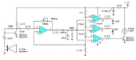
The circuit below responds to sound pressure levels from about 60 to 70 dB. The sound is picked up by an 8 ohm speaker, amplified by a transistor stage and one LM324 op-amp section. You can also use a dynamic microphone but I found the speaker was more sensitive. The remaining 3 sections of the LM324 quad op-amp are used as voltage comparators and drive 3 indicator LEDs or incandescents which are spaced about 3dB apart. An additional transistor is needed for incandescent lights as shown with the lower lamp. I used 12 volt, 50mA lamps. Each light represents about a 3dB change in sound level so that when all 3 lights are on, the sound level is about 4 times greater than the level needed to light one lamp. The sensitivity can be adjusted with the 500K pot so that one lamp comes on with a reference sound level. The other two lamps will then indicate about a 2X and 4X increase in volume.
In operation, with no input, the DC voltage at pins 1,2 and 3 of the op-amp will be about 4 volts, and the voltage on the (+) inputs to the 3 comparators (pins 5,10,12) will be about a half volt less due to the 1N914 diode drop. The voltage on the (-) comparator inputs will be around 5.1 and 6.5 which is set by the 560 and 750 ohm resistors.
When an audio signal is present, the 10uF capacitor connected to the diode will charge toward the peak audio level at the op-amp output at pin 1. As the volume increases, the DC voltage on the capacitor and also (+) comparator inputs will increase and the lamp will turn on when the (+) input goes above the (-) input. As the volume decreases, the capacitor discharges through the parallel 100K resistor and the lamps go out. You can change the response time with a larger or smaller capacitor.
This circuit requires a well filtered power source, it will respond to very small changes in supply voltage, so you probably will need a large filter capacitor connected directly to the 330 ohm resistor. I managed to get it to work with an unregulated wall transformer power source, but I had to use 4700uF. It worked well on a regulated supply with only 1000uF. (View)
View full Circuit Diagram | Comments | Reading(0)
Analog Milliamp Meter Used as Voltmeter
Published:2012/10/19 0:39:00 Author:muriel | Keyword: Analog , Milliamp Meter, Voltmeter
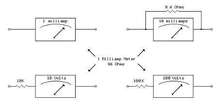
A milliamp meter can be used as a volt meter by adding a series resistance. The resistance needed is the full scale voltage reading divided by the full scale current of the meter movement. So, if you have a 1 milliamp meter and you want to read 0-10 volts you will need a total resistance of 10/.001 = 10K ohms. The meter movement itself will have a small resistance which will be part of the total 10K resistance, but it is usually low enough to ignore. The meter in the example below has a resistance of 86 ohms so the true resistor value needed would be 10K-86 or 9914 ohms. But using a 10K standard value will be within 1% so we can ignore the 86 ohms. For a full scale reading of 1 volt, the meter resistnace would be more significant since it would be about 8% of the total 1K needed, so you would probably want to use a 914 ohm resistor, or 910 standard value. The milliamp meter can also be used to measure higher currents by adding a parallel resistance. The meter resistance now becomes very significant since to increase the range by a factor of ten, we need to bypass 9/10 of the total current with the parallel resistor. So, to convert the 1 milliamp meter to a 10 milliamp meter, we will need a parallel resistor of 86/9 = 9.56 ohms. (View)
View full Circuit Diagram | Comments | Reading(1560)
LED VU Meter
Published:2012/10/19 0:38:00 Author:muriel | Keyword: LED VU, Meter
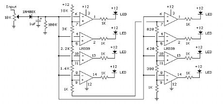
The circuit below uses two quad voltage comparators (LM339) to illuminate a series of 8 LEDs indicating volume level. Each of the 8 comparators is biased at increasing voltages set by the voltage divider so that the lower right LED comes on first when the input is about 400 millivolts or about 22 milliwatts peak in an 8 ohm system. The divider voltages are set so that each LED represents about twice the power level as the one before so the scale extends from 22 milliwatts to about 2.5 watts when all LEDs are lit. The sensitivity can be decreased with the input control to read higher levels. I have not built or tested this circuit, so please let me know if you have problems getting it working. The power levels should be as follows:
1 LED = 22mW
2 LEDs = 42mW
3 LEDs = 90mW
4 LEDs = 175mW
5 LEDs = 320mW
6 LEDs = 650mW
7 LEDs = 1.2 Watts
8 LEDs = 2.5 watts
(View)
View full Circuit Diagram | Comments | Reading(3677)
3.6 Volt cell phone battery meter
Published:2012/10/19 0:38:00 Author:muriel | Keyword: 3.6 Volt, cell phone , battery meter
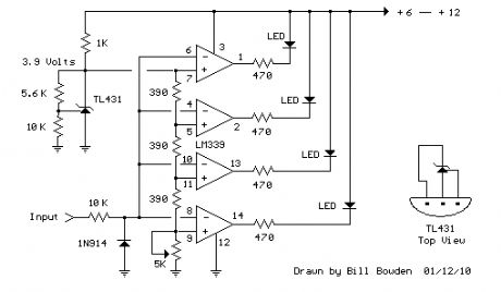
This is a similar circuit to the above and provides a 4 LED bar graph indicating the voltage of a common 3.6 volt Lithium - Ion recharable cell phone battery. The reference voltage is provided by a TL431 programmable voltage source which is set to 3.9 volts where the TL431 connects to the 1K resistor. The lower reference for the LED at pin 14 is set with the 5K adjustable resistor.
The programmed voltage of the TL431 is worked out with a voltage divider (10K 5.6K). The adjustment terminal or junction of the two resistors is always 2.5 volts. So, if we use a 10K resistor from the adjustment terminal to ground, the resistor current will be 2.5/10000 = 250uA. This same current flows through the upper resistor (5.6K) and produces a voltage drop of .00025 * 5600 = 1.4 volts. So the shunt regulated output voltage at the cathode of the TL431 will be 2.5 + 1.4, or 3.9 volts.
Working out the LED voltages, there are three 390 ohm resistors in series with another adjustable (5K) resistor at the bottom. Assuming the bottom resistor is set to 2K ohms, the total resistance is 390+390+390+2000 = 3170 ohms. So, the resistor current is the reference voltage (3.9) divided by the total resistance, or about 3.9/ (390 + 390 + 390 + 2000) equals 1.23 mA. This gives us about .00123*2000= 2.46 volts for the bottom LED, and about .00123*390 = .48 volts for each step above the bottom. So, the LEDs should light at steps of 2.46, 2.94, 3.42, and 3.9. A fully charged cell phone battery is about 4.2 volts. You can adjust the 5.6K resistor to set the top voltage higher or lower, and adjust the lower 5K resistor to set the bottom LED for the lowest voltage. But you do need a 6 to 12 volt or greater battery to power the circuit. (View)
View full Circuit Diagram | Comments | Reading(1816)
LED 12 Volt Lead Acid Battery Meter
Published:2012/10/19 0:37:00 Author:muriel | Keyword: LED, 12 Volt, Lead Acid, Battery Meter

In the circuit below, a quad voltage comparator (LM339) is used as a simple bar graph meter to indicate the charge condition of a 12 volt, lead acid battery. A 5 volt reference voltage is connected to each of the (+) inputs of the four comparators and the (-) inputs are connected to successive points along a voltage divider. The LEDs will illuminate when the voltage at the negative (-) input exceeds the reference voltage. Calibration can be done by adjusting the 2K potentiometer so that all four LEDs illuminate when the battery voltage is 12.7 volts, indicating full charge with no load on the battery. At 11.7 volts, the LEDs should be off indicating a dead battery. Each LED represents an approximate 25% change in charge condition or 300 millivolts, so that 3 LEDs indicate 75%, 2 LEDs indicate 50%, etc. The actual voltages will depend on temperature conditions and battery type, wet cell, gel cell etc. Additional information on battery maintenance can be found at: Battery Maintenance Tutorial (View)
View full Circuit Diagram | Comments | Reading(2779)
Telephone Ring Generator Using Small Power Transformer
Published:2012/10/19 0:36:00 Author:muriel | Keyword: Telephone Ring, Generator, Power Transformer
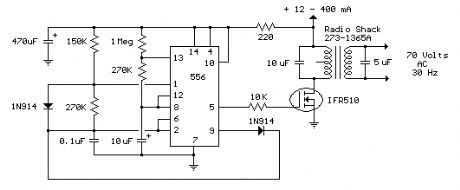
This ring generator will ring a telephone once every 10 seconds. The interval between rings can be lengthened or shortened by varying the value of the 1 Meg resistor. The 70 volt/ 30 Hz ring voltage is produced from the 120 volt side of a small 12.6 VAC power transformer (Radio Shack 273-1365). Both capacitors connected across the transformer windings are non-polarized / 100 volts. Circuit draws about 300mA from the 12 volt DC power supply during the ringing interval. (View)
View full Circuit Diagram | Comments | Reading(1762)
Telephone Ring Generator Using Switching Supply
Published:2012/10/18 22:58:00 Author:muriel | Keyword: Telephone Ring, Generator , Switching Supply
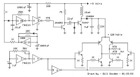
The telephone ring generator shown below generates the needed high voltage from a simple switching mode power supply (SMPS) which employs a CMOS Schmitt Trigger square wave oscillator, 10 mH inductor, high voltage switching transistor (TIP47 or other high voltage, 1 amp transistor) and a driver transistor (2N3053). The inductor should have a low DC resistance of 1.5 ohms or less. The switching supply must have a load connected to prevent the voltage from rising too high, so a 22K resistor is used across the output which limits the voltage to about 120 DC with the phone ringer disconnected and about 90 volts DC connected. The output voltage can be adjusted by changing the value of the 150K resistor between pins 10 and 11 which will alter the oscillator frequency (frequency is around 800 Hz as shown). The supply is gated on and off by a second Schmitt Trigger oscillator (pins 12/13) so that the phone rings for about 2 seconds and then the circuit idles for about a minute between rings. These times can be adjusted with the 10K and 300K resistors connected to pin 12. The push button shown is used to manually ring the phone. The 25Hz ringing frequency is generated by another Schmitt Trigger oscillator (pins 1/2) which controls the H bridge transistor output circuit. The 6 transistors in the output stage (4 NPN, 2 PNP) should be high voltage types rated at 200 volts collector to emitter or more. The ringer will only draw around 10 mA, so the output transistors can have a low current rating but must have a high voltage rating. I used TIP47s and small signal PNPs of unknown numbers that I had on hand, but other types such as NTE287 (NPN) and NTE288 (PNP) should work. Both have a 300 volt C-E rating and cost about $0.95 from mail order houses.
The two 470 ohm resistors connected to the output serve to limit the current in case the output is shorted. I never tried shorting the output to see how effective the resistors are, but I did lose a couple transistors and then decided to add the resistors. They should limit the surge to around 120 mA which should be low enough to prevent damage. The circuit draws around 250 mA when the ring signal is present so if you want to operate it from batteries, six 'D' type alkaline cells are recommended. It probably won't work with a small 9 volt battery.
(View)
View full Circuit Diagram | Comments | Reading(1893)
Generating Long Time Delays
Published:2012/10/18 22:58:00 Author:muriel | Keyword: Generating, Long Time , Delays
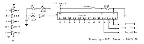
Generating long delays of several hours can be accomplished by using a low frequency oscillator and a binary counter as shown below. A single Schmitt Trigger inverter stage (1/6 of 74HC14) is used as a squarewave oscillator to produce a low frequency of about 0.5 Hertz. The 10K resistor in series with the input (pin 1) reduces the capacitor discharge current through the inverter input internal protection diodes if the circuit is suddenly disconnected from the supply. This resistor may not be needed but is a good idea to use.
The frequency is divided by two at each successive stage of the 12 stage binary counter (CD4040) which yields about 1 hour of time before the final stage (Q12) switches to a high state. Longer or shorter times can be obtained by adjusting the oscillator frequency or using different RC values. Each successive stage changes state when the preceding stage switches to a low state (0 volts), thus the frequency at each stage is one half the frequency of the stage before. Waveform diagrams are shown for the last 3 stages. To begin the delay cycle, the counter can be reset to zero by momentarily connecting the reset line (pin 11) to the positive supply. Timing accuracy will not be as good as with a crystal oscillator and may only be around 1 or 2% depending on the stability of the oscillator capacitor. (View)
View full Circuit Diagram | Comments | Reading(867)
32.768 KHz oscillator using a watch crystal
Published:2012/10/18 22:56:00 Author:muriel | Keyword: 32.768 KHz , oscillator, watch crystal
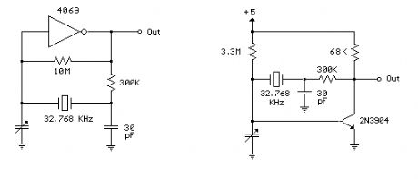
Below are a couple circuits you can use to produce a 32.768 KHz square wave from a common watch crystal. The output can be fed to a 15 stage binary counter to obtain a 1 second square wave. The circuit on the left using the 4069 inverter is recommended over the transistor circuit and produces a better waveform. The single transistor circuit produces more of a ramping waveform but the output swings the full supply voltage range so it will easily drive the input to a CMOS binary counter. (View)
View full Circuit Diagram | Comments | Reading(2075)
1 Second Time Base From Crystal Oscillator
Published:2012/10/18 22:52:00 Author:muriel | Keyword: 1 Second Time, Crystal Oscillator
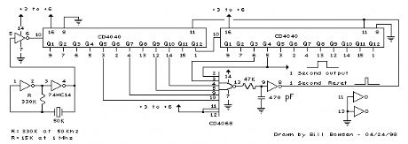
At 1 Mhz, the 330K resistor in the oscillator circuit will need to be reduced proportionally to about 15K. When the terminal count is reached, a 7 uS reset pulse is generated by the Schmitt Trigger inverter stage that follows the NAND gate. The 47K resistor and 470 picofarad capacitor sustain the output so that the counters are reliably reset to zero. This is less than one clock cycle at 50Khz and does not introduce an error but would amount to 7 cycles at 1 MHz which would cause the counters to lose 7 microseconds of time per second. It's not much of an error (7 parts in a million) but it would be there. The minimum reset pulse width for the 4040 CMOS counters is about 1.5 uS, so the reset pulse cannot be made much shorter. (View)
View full Circuit Diagram | Comments | Reading(1097)
Simple Op-Amp Radio
Published:2012/10/18 22:46:00 Author:muriel | Keyword: Simple , Op-Amp Radio
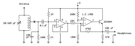
This is basically a crystal radio with an audio amplifier which is fairly sensitive and receives several strong stations in the Los Angeles area with a minimal 15 foot antenna. Longer antennas will provide a stronger signal but the selectivity will be worse and strong stations may be heard in the background of weaker ones. Using a long wire antenna, the selectivity can be improved by connecting it to one of the taps on the coil instead of the junction of the capacitor and coil. Some connection to ground is required but I found that standing outside on a concrete slab and just allowing the long headphone leads to lay on the concrete was sufficient to listen to the local news station (KNX 1070). The inductor was wound with 200 turns of #28 enameled copper wire on a 7/8 diameter, 4 inch length of PVC pipe, which yields about 220 uH. The inductor was wound with taps every 20 turns so the diode and antenna connections could be selected for best results which turned out to be 60 turns from the antenna end for the diode. The diode should be a germanium (1N34A type) for best results, but silicon diodes will also work if the signal is strong enough. The carrier frequency is removed from the rectified signal at the cathode of the diode by the 300 pF cap and the audio frequency is passed by the 0.1uF capacitor to the non-inverting input of the first op-amp which functions as a high impedance buffer stage. The second op-amp stage increases the voltage level about 50 times and is DC coupled to the first through the 10K resistor. If the pairs of 100K and 1 Meg resistors are not close in value (1%) you may need to either use closer matched values or add a capacitor in series with the 10K resistor to keep the DC voltage at the transistor emitter between 3 and 6 volts. Another approach would be to reduce the overall gain with a smaller feedback resistor (470K). High impedance headphones will probably work best, but walkman stereo type headphones will also work. Circuit draws about 10 mA from a 9 volt source. Germanium diodes (1N34A) types are available from Radio Shack, #276-1123. (View)
View full Circuit Diagram | Comments | Reading(1497)
Sunrise Lamp
Published:2012/10/18 22:45:00 Author:muriel | Keyword: Sunrise Lamp
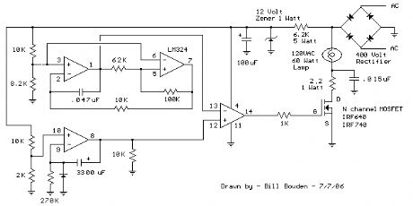
In this circuit, a 120VAC lamp is slowly illuminated over a approximate 20 minute period. The bridge rectifier supplies 120 DC to the MOSFET and 60 watt lamp. A 6.2K, 5 watt resistor and zener diode is used to drop the voltage to 12 volts DC for the circuit power. The bridge rectifier should be rated at 200 volts and 5 amps or more. In operation, a 700 Hz triangle waveform is generated at pin 1 of the LM324 and a slow rising voltage is obtained at pin 8. These two signals are compared at pins 12 and 13 to produce a varying duty cycle rectangular waveform at pin 14, which controls the MOSFET and brightness of the 60 watt lamp. When power is applied, the lamp will start to illuminate within a minute or so, and will slowly brighten to full intensity in about 20 minutes. You can make that longer or shorter with adjustments to the 270K resistor at pin 9. The 2.2 ohm resistor and .015uF cap connected to the lamp serve to supress RFI. The diode at pin 9 and 10K resistor on pin 8 are used to discharge the 3300uF cap when power is removed. Power should be off for a few minutes before re-starting.
Caution: This circuit is connected directly to the AC line and presents a hazard if any part is touched while connected to the line. Use caution and do not touch any parts while the circuit is connected to the AC line. You may want to use a 9 volt battery connected across the 12 volt zener to check the basic operation. The DC voltage at pins 1,2,3,5,6,7 will all be around 4.3 volts if the circuit is working correctly. If the DC voltages are all correct, you can use a variac to slowly apply the full line voltage and check for proper operation. (View)
View full Circuit Diagram | Comments | Reading(1230)
1.5 Hour Lamp Fader (Sunset Lamp)
Published:2012/10/18 22:44:00 Author:muriel | Keyword: 1.5 Hour , Lamp Fader , Sunset Lamp
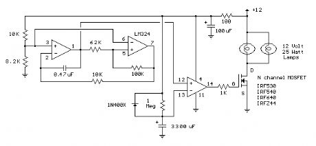
Similar to the one above, the sunset lamp comes on at full brightness and then slowly fades out over 1.5 hours time and stays off until power is recycled. (View)
View full Circuit Diagram | Comments | Reading(888)
| Pages:299/2234 At 20281282283284285286287288289290291292293294295296297298299300Under 20 |
Circuit Categories
power supply circuit
Amplifier Circuit
Basic Circuit
LED and Light Circuit
Sensor Circuit
Signal Processing
Electrical Equipment Circuit
Control Circuit
Remote Control Circuit
A/D-D/A Converter Circuit
Audio Circuit
Measuring and Test Circuit
Communication Circuit
Computer-Related Circuit
555 Circuit
Automotive Circuit
Repairing Circuit