
Circuit Diagram
Index 283
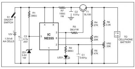
MOBILE CELLPHONE CHARGERS
Published:2012/11/8 1:09:00 Author:muriel | Keyword: MOBILE CELLPHONE, CHARGERS
View full Circuit Diagram | Comments | Reading(1230)
12-VOLT GEL CELL CHARGER
Published:2012/11/8 1:08:00 Author:muriel | Keyword: 12-VOLT, GEL CELL CHARGER
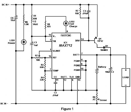
Recently, a fellow amateur was looking for a gel cell charger which would first charge at a fixed rate and then later switch to a trickle charge when the cell was fully charged. After reviewing several catalogs and web sites, the MAX712 IC was discovered. This IC meets all the requirements for almost any type of battery charging system. The circuit in Figure 1 was designed specifically for 12 volt gel cells.
When a discharged gel cell is connected, the charger goes into a fast charge mode at a fixed rate of 400 ma. After the chip detects the voltage leveling off or when 4 1/2 hours has elapsed. (which ever happens first.) the fast charge will stop. After the fast charge has ended, the IC goes into a trickle charge rate of about 50 ma. This trickle charge continues until 13.8 volts is reached which will stop all charging current since the cell is now fully charged. If the cell voltage should drop for any reason, either a fast charge or trickle charge (IC will detect what is needed) will start again.
When constructing this circuit, be sure to attach a small heat sink to Q1. Apply a DC (partially filtered) voltage of at least 15.3 volts. The voltage must never go below this level even under load conditions. Many of the DC wall transformers available will work just fine as long as they meet the minimum voltage requirement. The input voltage can be as high as 24 volts. If the input voltage must be in the 30 volt range, increase R1 to about 820 ohms.
The output voltage must be aligned prior to use. Disconnect the battery from the circuit and apply power. Connect a digital volt meter or other accurate volt meter to pin 2 (positive lead) and to pin 12 (negative lead). Adjust R7 until exactly 13.8 volts is read.
Because this circuit will not overcharge a gel cell, the battery can be connected indefinitely. This circuit is designed primarily as a 12 backup system and can be connected to the load provided the device to be powered only draws current during power line interruptions. Use a diode from the battery to load if needed. This circuit makes an excellent battery backup to an amateur transceiver.
The MAX712 IC and the .62 ohm resistor are available from Digi-Key, 701 Brooks Ave, Thief River Falls, MN 56701 (1-800-344-4539). Order part numbers MAX712CPE-ND and 0.62W-1-ND respectively. All other parts are available at Radio Shack. (View)
View full Circuit Diagram | Comments | Reading(0)
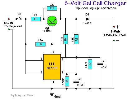
6-V gel cell charger
Published:2012/11/8 1:07:00 Author:muriel | Keyword: 6-V, gel cell charger
View full Circuit Diagram | Comments | Reading(1067)
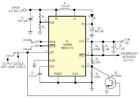
Dual-Voltage Supply Powers SIM Card
Published:2012/11/8 1:07:00 Author:muriel | Keyword: Dual-Voltage, Supply , Powers SIM Card
View full Circuit Diagram | Comments | Reading(1646)
Cell Phone Helper
Published:2012/11/8 1:05:00 Author:muriel | Keyword: Cell Phone Helper
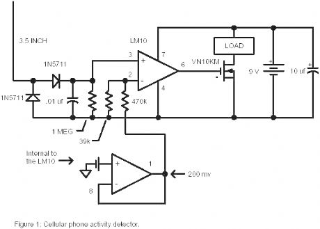
For times when a loud beeping is unacceptable, the load could be a small motor with an offset weight on the shaft so that it vibrates when the phone receives a call. (Add a switch in series with the battery for this application to stop the vibration while you talk.) Or the load could be a lamp or lamp/flasher circuit for a visual indication of an incoming call. The load could be a timer, tape recorder, or even an interrupt line on your laptop to bring up a call logging program. (That one might be rather challenging.) At the other extreme, the detector could be used to generate a louder ringing signal or even honk the horn for when you leave the phone in the car. The circuit will work well from the car’s 12 volt battery and the current consumption is so low that a power switch is not included. The only critical wiring involves the diodes, antenna, and .01uf capacitor. Keep these leads short and the circuit should work fine. If the sensitivity is too high then increase the value of the 39k resistor. Other RF Schottky diodes or fast silicon diodes may be substituted and even 1N914s may work adequately well. Use insulated wire for the antenna and keep it fairly straight although bending the antenna to fit inside a small plastic enclosure won’t hurt the performance much. Substitute a cmos op-amp for the LM10 with different voltage divider values for the trigger reference to reduce the standby current to virtually nothing for applications powered by tiny batteries. (View)
View full Circuit Diagram | Comments | Reading(1301)
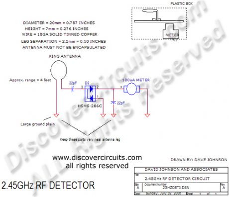
2.45GHz RF Signal Detector
Published:2012/11/8 0:59:00 Author:muriel | Keyword: 2.45GHz , RF Signal Detector
View full Circuit Diagram | Comments | Reading(1560)
Cellular Telephones/Cameras
Published:2012/11/8 0:51:00 Author:muriel | Keyword: Cellular Telephones/Cameras
View full Circuit Diagram | Comments | Reading(1062)
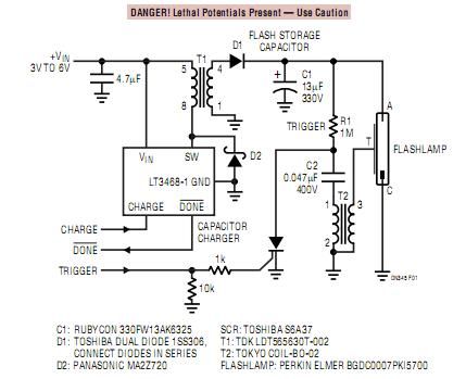
3 different Xenon flashing circuits
Published:2012/11/8 0:49:00 Author:muriel | Keyword: 3 different , Xenon , flashing circuits
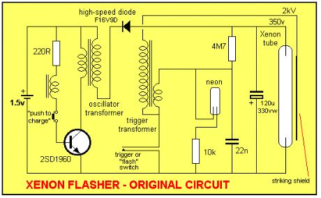
This discussion covers 3 different Xenon flashing circuits from disposable cameras. From them, you will learn circuit tricks that have NEVER been shown in any theory book.The first circuit covers 6 BUILDING BLOCKS.You will need an old disposable Flash Camera plus two extra parts to carry out the modifications. (View)
View full Circuit Diagram | Comments | Reading(3593)
LD168 audio voltage-controlled flasher decorationcontrol circuit
Published:2012/11/7 19:25:00 Author:Ecco | Keyword: audio , voltage-controlled flasher, decorationcontrol circuit
In the figure, LD168 is a tape recorders flasher ASIC for speaker sound level indication. It has four outputs which can directly drive a plurality of light-emitting diodes, and it can also drive lantern light emitting SCR devices.
(View)
View full Circuit Diagram | Comments | Reading(807)
5G167 audio voltage-controlled two-way water lantern control circuit
Published:2012/11/7 20:17:00 Author:Ecco | Keyword: audio, voltage-controlled , two-way water , lantern control
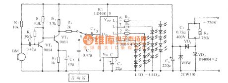
In the circuit shown in Figure, 5G167 is the recorders rotary lighting Speaker control ASIC produced by Shanghai elements factory 5; HTD is the sensor which can convert acoustic signal into a corresponding electrical signal.
(View)
View full Circuit Diagram | Comments | Reading(1199)
5GM168 audio voltage-controlled dance halls decorative lantern with birdsong sound circuit
Published:2012/11/7 20:14:00 Author:Ecco | Keyword: audio , voltage-controlled , dance halls , decorative lantern , birdsong sound
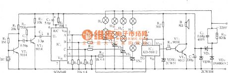
As shown in the figure, it uses the audio voltage-controlled lantern control integrated circuit 5GM168 as the core, and it is matched with birds sound and audio amp circuit to form the audio voltage-controlled lantern and birdsong sound circuit.
(View)
View full Circuit Diagram | Comments | Reading(738)
5GMl68 audio voltage-controlled holiday lights control circuit
Published:2012/11/7 20:11:00 Author:Ecco | Keyword: audio , voltage-controlled , holiday lights control
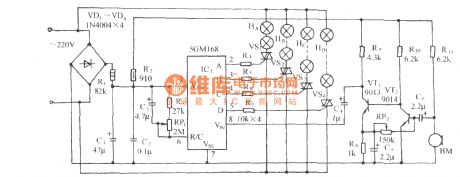
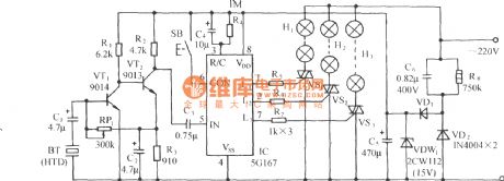
As shown in figure, it is a four-way lantern control circuit using 5GM168(chip's G- foot is vacant ), four-way outputs are added to the gate pole of VS1 ~ VS4 by current limiting resistor to control their on-off and light accordingly Road lanterns. BM is a pickup sensor.
(View)
View full Circuit Diagram | Comments | Reading(1067)
Pulse position modulating circuit with 555 time-base circuit
Published:2012/11/7 19:55:00 Author:Ecco | Keyword: Pulse position modulating , 555, time-base circuit
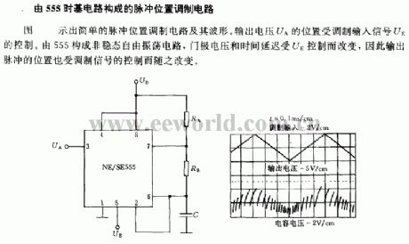
The figure illustrates a simple pulse -position modulation circuit and its waveform. The position of output voltage UA is controlled by the modulation input signal UE. 555 constitute a non - steady-state free oscillation circuit, and the gate voltage and time delay is changed by the UE control, therefore the position of the output pulses is controlled by the modulation signal.
(View)
View full Circuit Diagram | Comments | Reading(1732)
Inverter speed control circuit with a frequency meter operation box
Published:2012/11/6 20:26:00 Author:Ecco | Keyword: Inverter , speed control , frequency meter, operation box

FR-AX is a frequency meter operation box. This operation box has the frequency meter and frequency setting potentiometer (it is not shown in figure) for manual control of the inverter to achieve positive and reverse speed and self - start control.
(View)
View full Circuit Diagram | Comments | Reading(1531)
AIDS key circuit with Hall transmitter
Published:2012/11/6 20:40:00 Author:Ecco | Keyword: AIDS key , Hall transmitter
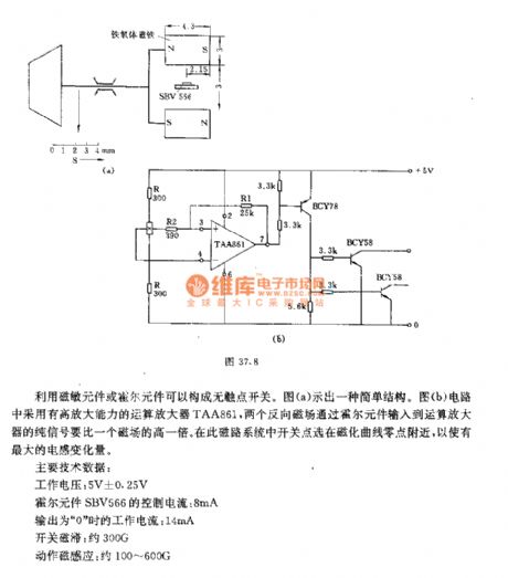
It uses magnetic components or Hall element to form a non-contact switch. Figure a shows a simple structure. The circuit shown in Figure b uses the operational amplifier TAA861 with high amplification capability, two reverse magnetic fields input the pure signal to operational amplifier through the Hall element is twice of a magnetic field. In this magnetic circuit system, switch tap is near zero point of the magnetization curve to make the maximum inductance variation amount.
(View)
View full Circuit Diagram | Comments | Reading(1235)
Magnetic terminal switch circuit
Published:2012/11/6 20:55:00 Author:Ecco | Keyword: Magnetic terminal , switch
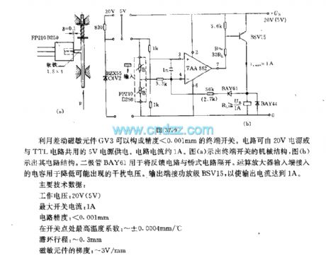
The differential magnetic sensing element GV3 can constitute terminal switch with accuracy <0.001mm. The circuit can be supplied by 20V power supply or 5V power supply shared with TTL circuit. Circuit current is about 1A. Figure A shows a mechanical structure of the terminal switch, b shows the circuit structure. Diode BAY61 is used to separate the feedback circuit and bridge circuit. The capacitor connected to the op amp input terminal is used to reduce possible interference voltage.
(View)
View full Circuit Diagram | Comments | Reading(1061)
Single-phase motor reactor buck speed control Circuit
Published:2012/11/6 21:22:00 Author:Ecco | Keyword: Single-phase motor , reactor, buck, speed control
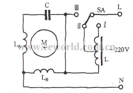
As shown in figure, the reactor is connected to the single-phase motor supply circuit in series, and the buck governor is realized by switching reactor coil tap. When the governor switch SA is set to the I , the main winding LR and reactor L is cascaded to power supply, the power supply voltage will be landed on the entire coil of the reactor L, and thus the voltage of main winding LR reduces, then the field generated by LR is weakening, the slip of the motor increases, the speed is significantly reduced; SA is set to Ⅲ , the main windingoperates under the rated voltage, the speed will be the highest; SA is set to II , it has the medium speed.
(View)
View full Circuit Diagram | Comments | Reading(1946)
Single-phase motor winding tap H connection three-speed circuit
Published:2012/11/6 21:27:00 Author:Ecco | Keyword: Single-phase motor, winding tap , H connection , three-speed

The circuit is shown as the figure. After the speed winding LD and auxiliary winding LA are connected in series, then they are connected between main winding LR's tap and power supply. LD and LA are in the same groove with the same phase. Speed control principle: the circuit make LR upper part, the second part and auxiliary winding LA part form inconsistent-phase three asymmetric phases.
(View)
View full Circuit Diagram | Comments | Reading(3390)
The single-phase motor connected capacitor series-parallel three-speed circuit
Published:2012/11/5 20:20:00 Author:Ecco | Keyword: single-phase motor , connected capacitor, series-parallel , three-speed
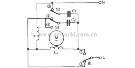
When it is governing, the primary and secondary windings can be connected in series to achieve a buck governor. If the capacitor is connected to auxiliary winding La in parallel, it will play a phase-shifting effect on LA current to change to a different electric capacity and get different rotational speed. When it runs at a high speed, switches S1 , S2 are put in the illustrated position; when it is in the medium speed, S1 is ON, S2 is turned to the position of ④; when it is in a low speed, S1 is connected to ②, S3 is turned to ⑤. The capacity of C1 should be less than the capacity of C2 in circuit.
(View)
View full Circuit Diagram | Comments | Reading(2403)
Single-phase motor winding tap L-1 connection three-speed circuit
Published:2012/11/5 20:26:00 Author:Ecco | Keyword: Single-phase motor, winding tap , L-1 connection , three-speed
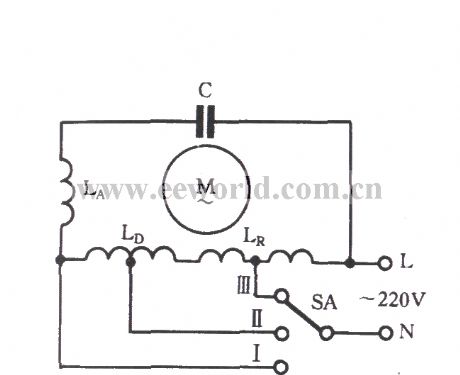
The speed control switch SA increases a medium-speed gear. When SA is allocated to the medium speed II , a part of the governor winding is connected to the auxiliary winding LA, another part is connected in series to the main winding LR, so that the motor is running in the medium speed. The characteristics of the L-1 connection: the main winding LR and governor winding LD are distributed in the same slot with the same phase, and all the windings are involved in the high, medium and low speed operation.
(View)
View full Circuit Diagram | Comments | Reading(4578)
| Pages:283/2234 At 20281282283284285286287288289290291292293294295296297298299300Under 20 |
Circuit Categories
power supply circuit
Amplifier Circuit
Basic Circuit
LED and Light Circuit
Sensor Circuit
Signal Processing
Electrical Equipment Circuit
Control Circuit
Remote Control Circuit
A/D-D/A Converter Circuit
Audio Circuit
Measuring and Test Circuit
Communication Circuit
Computer-Related Circuit
555 Circuit
Automotive Circuit
Repairing Circuit