
Circuit Diagram
Index 290
A simple audio power meter circuit using LM3915
Published:2012/10/28 21:11:00 Author:Ecco | Keyword: audio power meter
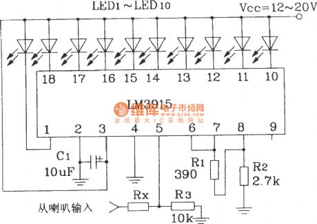
Note: If the speaker internal resistance is 4Ω, Rx takes 10kΩ If the speaker internal resistance is 8Ω, Rx takes 18kΩ If the speaker internal resistance is 16Ω, Rx takes 30kΩIt uses IC to display AC input signal amplitude, and the more perfect method is to use a half - wave converter to change AC signal into DC signal, the DC signal is sent to the input terminal of IC.
(View)
View full Circuit Diagram | Comments | Reading(4589)
The static driver interface circuit of SAA1064 serial I2C bus LED display driver integrated circuit
Published:2012/10/28 21:15:00 Author:Ecco | Keyword: static driver , interface , serial I2C bus , LED display , driver integrated circuit
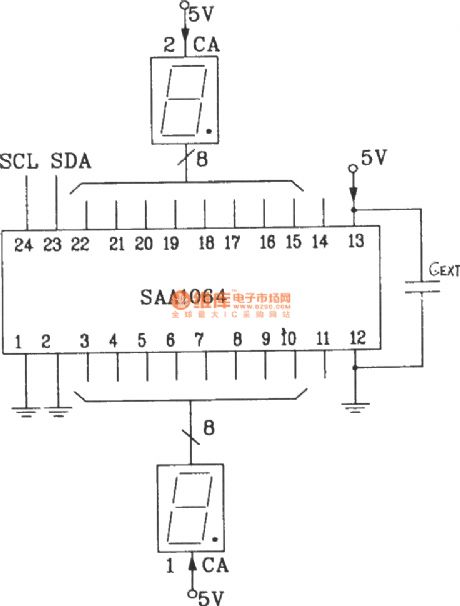
Under static working mode, LED does not require to add an external driver, but it directly uses two 8-bit output port driver. Vcc and VEE ends are adding decoupling capacitors, the general value is 0.01μF.
(View)
View full Circuit Diagram | Comments | Reading(1667)
10 -point LED level display circuit with 2 blocks of BA6104 5-bit LED level meter driver integrated circuits
Published:2012/10/28 22:04:00 Author:Ecco | Keyword: 10 -point, LED , level display , 2 blocks , 5-bit , LED level meter , driver integrated circuit

Regulation IC1's pin 7 Vref can light L1 ~ L5 in IC1; Regulation IC2's pin 7 Vref can light L1 ~ L5 in IC2, and the lighting voltage is 2 times of IC1, luminous order is from L1 ~ L5 of IC1 to L1 ~ L5 of IC2.
(View)
View full Circuit Diagram | Comments | Reading(2042)
The basic application circuit of BL6124 5-bit LED level meter driver integrated circuit
Published:2012/10/28 22:12:00 Author:Ecco | Keyword: basic application , 5-bit , LED level meter , driver integrated circuit
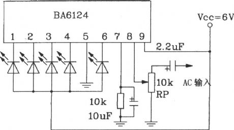
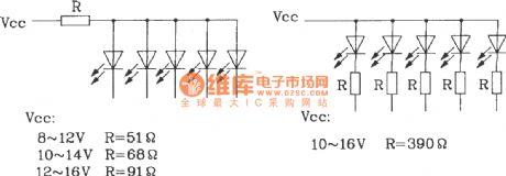
LED current limiting circuit is used to limit LED current, the LED can be connected to a resistor in parallel or in series, and the circuit is shown in (a ) , ( b ). When working voltage is higher than 9V, the LED current terminal should be added a shunt resistor, the specific circuit with different Vcc values is shown in Figure.
(View)
View full Circuit Diagram | Comments | Reading(2555)
Low-pass filter (Integrator) circuit
Published:2012/10/26 21:03:00 Author:Ecco | Keyword: Low-pass filter, Integrator
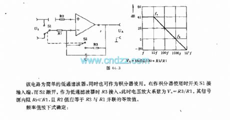
The circuit is a simple low-pass filter, but also can be used as an integrator. When it is used as integrator, switch S1 is connected to input end, while the S2 is disconnected. R3 is connected when it is used as lower filter, amplification coefficient of the voltage VU=R3/R1. The internal resistor Ri of signal source is much less than R1, and R2 value should be equal to the equivalent value of R3 and R1 connected in parallel.
(View)
View full Circuit Diagram | Comments | Reading(1160)
Ultrasonic liquid level remote control and indicator circuit
Published:2012/10/26 21:10:00 Author:Ecco | Keyword: Ultrasonic , liquid level , remote control, indicator
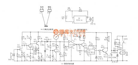
As shown in the figure, the circuit includes the ultrasonic transmitter and ultrasonic receiving and control circuir. It uses the characteristic that ultrasonic has a larger propagation loss in the air, and the propagation characteristics in different media such as gases, liquids. It use isolation-emitting ultrasonic technology shown in figure a to measure distance, liquid or material.
(View)
View full Circuit Diagram | Comments | Reading(4797)
NORELCO rechargeable electric shaver circuit
Published:2012/10/26 21:41:00 Author:Ecco | Keyword: NORELCO , rechargeable, electric shaver
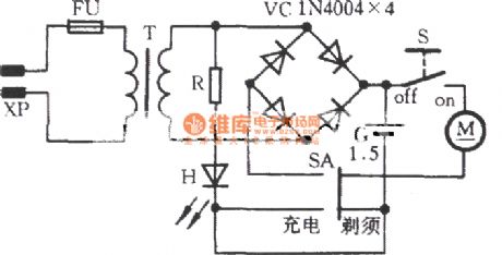
When it is charging, SA is put to charging , after XP is inserted into the 220V power outlet,T's secondary stage is 4V (unloaded), and it is charging for battery after being rectified by VC. Usually, a single charging time is 8-10 hours. H is the charging light which is illuminated when charging. When peopel use ot for shaving, switch SA is turned to shave position, then s is swicthed to on position, M rotary can make shaving. S is switched to off , the machine is turned off.
(View)
View full Circuit Diagram | Comments | Reading(4565)
PC machine CPU overheating language telling circuit
Published:2012/10/26 21:53:00 Author:Ecco | Keyword: PC machine , CPU overheating, language telling
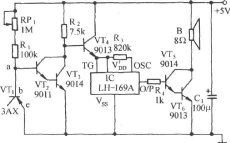
It consists of a temperature sensor, temperature control electronic switch and language telling circuit. In the summer season, central processing unit CPU on PC is often overheating, in the circuit, the tube core of VT1 is closed to radiator of CPU chip, once the CPU is overheating, the circuit will send out Please note the temperature to remind users to take cooling measures.
(View)
View full Circuit Diagram | Comments | Reading(1302)
PC control three-phase motor circuit for buck and starting
Published:2012/10/26 22:02:00 Author:Ecco | Keyword: PC control, three-phase motor, buck and starting
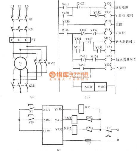
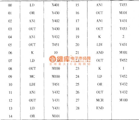
Figure (a) is the primary circuit which is a common Y-△ buck start circuit; Figure (b) is the Y-△ buck starting automatic control system circuit with FX2-40MR-Y PC design; Figure (c) shows the external wiring diagram of system.
(View)
View full Circuit Diagram | Comments | Reading(1292)
Preamp and 330 + MHz Prescaler
Published:2012/10/25 21:40:00 Author:muriel | Keyword: Prescaler, 330 + MHz
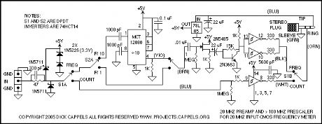
Signals applied to the input connector can be switched either through the AC path which includes the preamp and the prescaler, if switched into the circuit, or the DC path, which routes the signal to a Schmitt trigger buffer that then sends the signal on to the counter.Regardless of how the signal is routed, it must first pass through an input protection network, which includes two schottky diodes and a zener clamp. The 1N5711 schottky diodes prevent the input signal from going more than a schottky diode drop below ground or above the power supply. I used Schottky diodes because they have a lower voltage drop than the PN protection diodes on the CMOS integrated circuit they are intended to protect, and as such, they will draw much more of the current from excessive input voltages than the input protection diodes in the integrated circuits.The two 1N5226 zener diodes in series prevents the power supply from rising above 6.6 volts in case the input is accidentally connected to a low impedance source that is higher than 5 volts. The 47 Ohm resistor limits the input current in case of excessive voltage being applied to the inputs.The input of the frequency meter requires a full 5 volt CMOS logic swing, and the prescaler's output is less than 1 volt peak-to-peak, so the prescaler, when switched into the circuit, the signal goes through the prescaler, then the preamp, and the preamp drives the frequency meter through the Schmidt trigger buffers.The MCT10280 prescaler can be set to divide by 80, 40, 20, or 10, as a function of which pins are tied to the power supply. I set this one to divide by 10 since it is adequate for my needs, and the mental calculation of multiplying the meter reading by 10 is not taxing. One problem with the MCT10280 is that if it doesn't have an adequate input, the output is very noisy, which shows up as counts in the couple MHz range on the frequency meter. This noise shows up if the signal amplitude the signal frequency is too low. For this reason, I only intend to use the prescaler with inputs between 10 MHz and 300 MHz.
(View)
View full Circuit Diagram | Comments | Reading(1259)
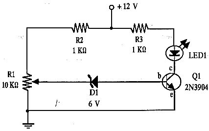
12 V LEAD-acid monitor
Published:2012/10/25 21:39:00 Author:muriel | Keyword: 12 V, LEAD-acid monitor
View full Circuit Diagram | Comments | Reading(964)
12v battery monitor
Published:2012/10/25 21:38:00 Author:muriel | Keyword: 12v battery monitor
View full Circuit Diagram | Comments | Reading(1848)
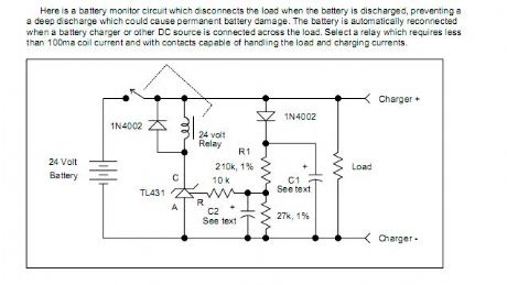
Battery Discharge Monitor
Published:2012/10/25 21:37:00 Author:muriel | Keyword: Battery Discharge Monitor
View full Circuit Diagram | Comments | Reading(1765)
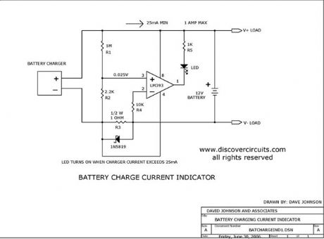
Battery Charge Current Indicator circuits
Published:2012/10/25 21:37:00 Author:muriel | Keyword: Battery Charge, Current Indicator circuits
View full Circuit Diagram | Comments | Reading(1985)
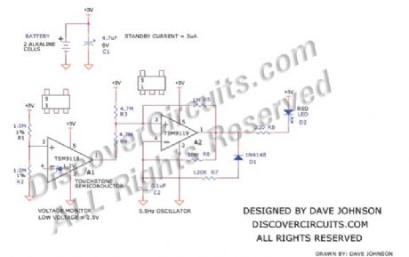
Alkaline Low Battery Voltage Indicator
Published:2012/10/25 21:36:00 Author:muriel | Keyword: Alkaline, Low Battery Voltage , Indicator
View full Circuit Diagram | Comments | Reading(1020)
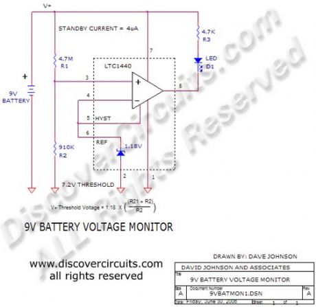
9v Battery Voltage Monitor
Published:2012/10/25 21:34:00 Author:muriel | Keyword: 9v , Battery Voltage Monitor
View full Circuit Diagram | Comments | Reading(999)
BattMan II: Build a Computer Controlled Battery Manager
Published:2012/10/25 21:32:00 Author:muriel | Keyword: BattMan II, Computer Controlled, Battery Manager
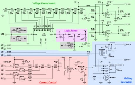
BattMan II consists of five subsystems: power supply, current control, battery connection, voltage measurement, and logic power.
The power supply I used is a commercial off-the-shelf model that can supply 18 Volts at 2.2 Amps. I purchased mine at a surplus store. Any similar power supply will do, so long as it produces 18 to 20 Volts, and enough current for the maximum charge rate you want to be able to use. Points labeled V+ in the schematic are connected to the positive terminal of the power supply.
CMOS buffers Z2a through Z2d together with resistors R26 through R34 form an R-2R ladder digital-to-analog converter. R34 is used to adjust the output voltage range so that it spans 0 to 0.2 Volts (which can be measured at test point TP2). The input to the converter is taken from the four low-order data bits (D0 to D3) of the parallel printer port that BattMan is connected to. (View)
View full Circuit Diagram | Comments | Reading(1533)
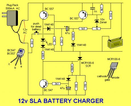
Battery Charger for 12V SLA
Published:2012/10/25 21:30:00 Author:muriel | Keyword: Battery Charger, 12V SLA
View full Circuit Diagram | Comments | Reading(2955)
The gain or programming amplifier PCB circuit diagram
Published:2012/10/25 21:05:00 Author:Ecco | Keyword: gain , programming, amplifier , PCB
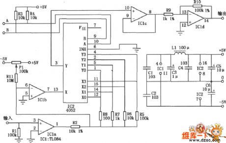
As shown in figure, the amplifier circuit can respectively provide 1, 10, 100, 1000 magnification factors under four kinds of logic level control, and each magnification bandwidth is greater than 30kHz, the entire circuit's current is less than 7mA under± 5V supply.
(View)
View full Circuit Diagram | Comments | Reading(1284)
High voltage DC switch circuit diagram
Published:2012/10/25 21:01:00 Author:Ecco | Keyword: High voltage , DC switch
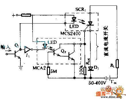
The circuit uses optical-isolation optoelectronic thyristor rectifier as high voltage DC switch. When MCA2 photoelectric Darlene Dayton circuit's Q1 divides current of the load through gate, then the silicon controlled rectifier's gate gets bypass, silicon controlled rectifier is turned off. If the pulse signal is added to appropriate light emitting diode, the circuit operates, so that the thyristors are turned on or off.
(View)
View full Circuit Diagram | Comments | Reading(1578)
| Pages:290/2234 At 20281282283284285286287288289290291292293294295296297298299300Under 20 |
Circuit Categories
power supply circuit
Amplifier Circuit
Basic Circuit
LED and Light Circuit
Sensor Circuit
Signal Processing
Electrical Equipment Circuit
Control Circuit
Remote Control Circuit
A/D-D/A Converter Circuit
Audio Circuit
Measuring and Test Circuit
Communication Circuit
Computer-Related Circuit
555 Circuit
Automotive Circuit
Repairing Circuit