
Circuit Diagram
Index 284
Single-phase motor winding tap L-2 connection two-speed circuit
Published:2012/11/5 20:39:00 Author:Ecco | Keyword: Single-phase motor, winding tap, L-2 connection, two-speed
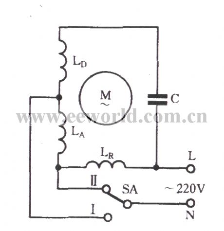
As shown in figure, in the L-2 connection, the governor winding LD and the auxiliary winding LA are embedded in the same groove, so they have the same phase. In the same slot, the governor winding LD is wound on the up position, the auxiliary winding LA is wound lower, and they have the same diameter. When SA is put to Ⅱ gear, motor speed is the maximu, the both ends of main winding LR are applied to the rating voltage; while it is in the position of I , LR is connected to governor winding LD in series, so the motor speed reduces.
(View)
View full Circuit Diagram | Comments | Reading(4592)
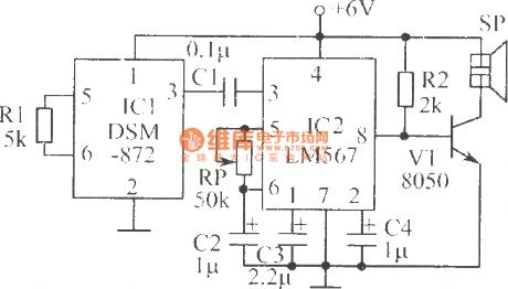
Voice switches ( for beginners making circuit diagram )
Published:2012/11/5 20:41:00 Author:Ecco | Keyword: Voice switches , beginners making
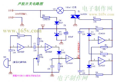
After the installation is complete, there are no errors in the circuit, then it can be used after being adjusted.
(View)
View full Circuit Diagram | Comments | Reading(960)
The roadblocks flashing alarm circuit ( 4 )
Published:2012/11/5 20:48:00 Author:Ecco | Keyword: roadblocks flashing, alarm
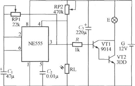
Road blocks flashing warning light using battery is shown in the figure, and it can be used local road facilities without AC power for roadblocks alarm. NE555, RP1 , RP2 , C1 , RL and RL form a a light -controlled self-excited multivibrator. Due to light exposure in daytime, it is in low resistance, NE555 forces reset terminal ④ feet level to be less than 0.4V, and the NE555 is mandatory reset, output end ③ feet is constant low, then VT1 and VT2 are cutoff, warning lights E does not shine. Due to RL has no light exposure in nighttime, it shows a high resistance, then it is divided by RP2 to make ④ feet level increase, when it is greater than 0.4V, you can lift the blockade on the circuit, the circuit is start-up.
(View)
View full Circuit Diagram | Comments | Reading(1201)
Textile machine automatic control circuit
Published:2012/11/4 20:22:00 Author:Ecco | Keyword: Textile machine, automatic control
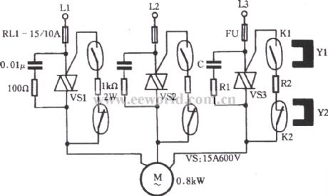
As shown in figure, VS is the triac, R1 and C form the absorption circuit, R2 is the trigger limit measured resistor. K1 is activated dry reed pipe, K2 is the stop dry reed pipe, Y1 , Y2 are the magnets. Sectional phase power L1, L2, L3 is applied to motor M via VS1 ~ VS3. When it is driving, promoting the clutch handle to make Y1 move to the boot position, K1's internal contacts are connected to trigger VS1 ~ VS3 conduction, the motor M is energized; when it is parking, the stop magnet Y2 on clutch handle is near K2, K2's internal normally closed contacts disconnects, trigger circuit is powered down, VS1 ~ VS3 are cut-off, the motor M stops.
(View)
View full Circuit Diagram | Comments | Reading(1480)
Induction heating automatic control circuit
Published:2012/11/4 20:53:00 Author:Ecco | Keyword: Induction heating , automatic control
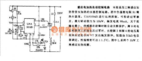
This figure uses labor - frequency induction heating pipe to control the heating water temperature. In Figure, load temperature sensitive resistor Rt is used to measure the temperature of hot water. UAA1016B can make proportional control, SCR is used for zero trigger, the maximum driving capacity is 10kW, trigger current is 90mA, and it can automatically shutdown for protection when sensor occurs failure.
(View)
View full Circuit Diagram | Comments | Reading(3055)
Inductive switch circuit
Published:2012/11/4 21:00:00 Author:Ecco | Keyword: Inductive switch
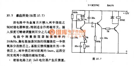
When the metal tongue in circuit is inserted between two windings, relay releases, it is especially suitable for the terminal switch. Insertion depth can be precisely adjusted to the hundredths of a millimeter. The circuit measured oscillator oscillation frequency is about 200kHz. The collector oscillation loop coils are wound on a ferrite segment core. The base feedback coil is wound on the other core. Two core relative distance is about 5 mm.
(View)
View full Circuit Diagram | Comments | Reading(995)
Intermittent operation circuit
Published:2012/11/4 21:11:00 Author:Ecco | Keyword: Intermittent operation
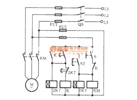
In some occasions, you need the motor to open and stop any time. This is called intermittent operation . The intermittent operation circuit is shown as the figure. In the Figure, S is a manual switch. Closing the S, KM and 1KT are simultaneously energized, KM main contact gets action, the motor M is running. After running for a period of time ( determined by 1KT time relay ), 1KT is delay closed, contacts are closed to turn on the relay K and other the relay 2KT circuit, K normally closed contacts disconnect, KM loses power, and M stops working.
(View)
View full Circuit Diagram | Comments | Reading(1054)
AC contactor power saving and silent running circuit 4
Published:2012/11/4 21:23:00 Author:Ecco | Keyword: AC contactor , power saving, silent running
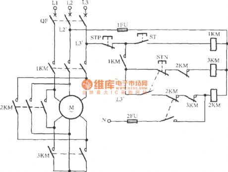
The circuit is shown in Figure, it uses Y-△ manually buck starter to realize AC contactor high voltage (380V) start and low-voltage (220V) operation, then it will get the power-saving and silent effect. Pressing the start button ST, 1KM is energized, its normally open contact is closed, 3KM is energized. The 3KM normally closed auxiliary contacts disconnects, the main contacts are closed, then the motor M winding is connected into a Y-shaped connection for the buck start. When the motor speed is up to or near rated speed, pressing the running button STN can make 3KM lose power and release, then 2KM gets electric (380V) and pulls, the motor M is switched to △ pick operation.
(View)
View full Circuit Diagram | Comments | Reading(1934)
Dual LEDs alternately flasher circuit
Published:2012/11/1 22:34:00 Author:Ecco | Keyword: Dual LEDs , alternately flasher
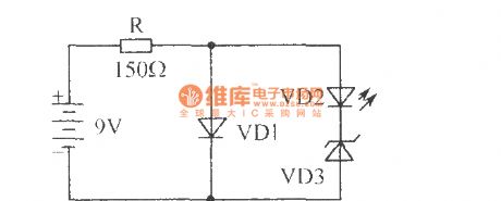
It only uses four elements to constitute an interesting two-tube alternately flasher circuit. VD1 is one flashing light-emitting diode, VD2 uses ordinary light-emitting diode. The working process: VD1 work requires 5V, 30mA. When it gets power, VD1 gets conduction, and there is about 5V voltage adding the series VD2 and VD3, VD3 is the 6.2V zener diode, so VD3 does not work, then only the VD1 is bright; when VD1 is intermittent bright, the supply voltage is added on VD2, VD3 through R current limiting, so VD3 regulator tube works, the current flows through VD2.
(View)
View full Circuit Diagram | Comments | Reading(1682)
Rapid heating, cooling beverage thermostat machine
Published:2012/11/1 22:51:00 Author:Ecco | Keyword: Rapid heating, cooling beverage , thermostat machine
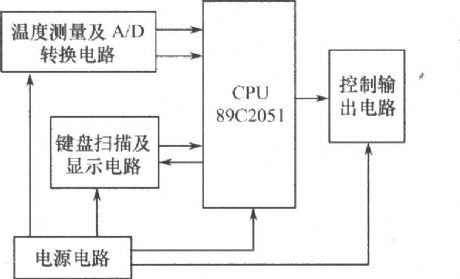


The hardware configuration of the thermostat machine system is composed of temperature measurement and A / D conversion circuit, signal testing and processing circuit, keyboard scan and display circuit, the control output circuit and power supply circuit. The system block diagram is shown below . ( 1 ) Signal testing and processing circuit: the core of the thermostat machine uses AT's cost-effective 8 - bit microcontroller AT89C2051, and it is used to complete the measurement and processing of the data and realize drinks temperature measurement and control function.
(View)
View full Circuit Diagram | Comments | Reading(1476)
Last stage power amplifier circuit diagram
Published:2012/11/1 22:28:00 Author:Ecco | Keyword: Last stage, power amplifier
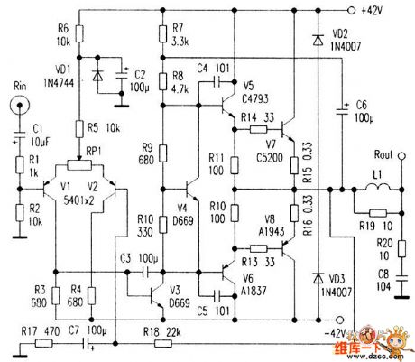
V1, V2 form a single-ended input, single-end output differential amplifier, V3 constitutes a voltage amplifier. In order to ensure that there is sufficient gain and distortion improvment, V4 is used for temperature compensation. V5, V6 are current push tubes which mainly provide the necessary current for the power amplifier tube to reduce the input impedance of the power amplifier tube. The high-power tube uses the recently popular ZSC5200/2SA1943 pairing tube. R18 is the negative feedback resistor, the closed-loop gain of the machine is determined by R18, R17, C6 is the bootstrap capacitor.
(View)
View full Circuit Diagram | Comments | Reading(2637)
The magnetic reset demagnetization network principle circuit diagram
Published:2012/11/1 22:20:00 Author:Ecco | Keyword: magnetic reset, demagnetization network
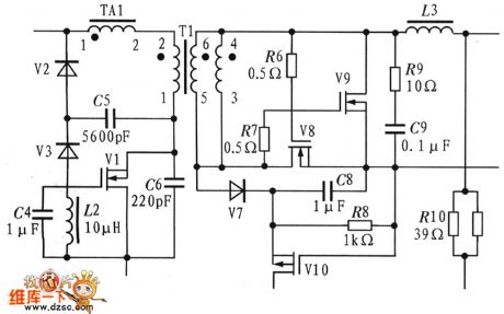
Magnetic reset circuit uses LCD network, and LCD Clamp not only be able to feedback transformer excitation energy back to the grid, and can effectively inhibit the voltage spikes caused by the leakage inductance energy. When V1 is off, C5 clamp capacitor is charged. When V1DS rises to greater than the input voltage, C5 discharges, and V2 gets conduction, when V1DS gets conduction, the inductor L2 and C5 are resonant and discharging forcing V1DS denitration decreased, and the circuit is shown as the figure.
(View)
View full Circuit Diagram | Comments | Reading(1231)
RJ-11 bridge circuit schematic
Published:2012/11/1 22:00:00 Author:Ecco | Keyword: bridge
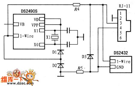
DS2490S is the bridge circuit of USB port and 1 - Wire device, which can be directly connected to the USB host system. It can produce strict timing and voltage slew rate controlled 1-Wire waveforms, and it can meet the requirements of the USB interface communication protocol to ensure normal USB port and l-Wire devices and securely communication.
(View)
View full Circuit Diagram | Comments | Reading(1270)
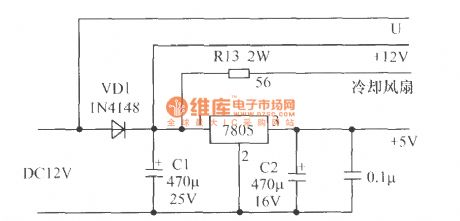
The overvoltage protection circuit
Published:2012/10/31 21:21:00 Author:Ecco | Keyword: Overvoltage protection
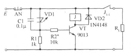
When the external voltage does not exceed the set E voltage Vs, negative resistance light-emitting diode VD1 it cutoff, VT is cutoff because of no base current, relay J does not pull in, and its normally closed contact J1-1 is closed to provide supply for the load RL. Once the external voltage E exceeds the set voltage Vs, VD1 gets conduction, VD1 emitting light to show overvoltage. The the capacitor C1 connected to VD1 in parallel is anti - electromagnetic interference, and it can be selected in the range of 0.01μF ~ 0.1μF.
(View)
View full Circuit Diagram | Comments | Reading(1405)
Logic level test circuit
Published:2012/10/31 21:20:00 Author:Ecco | Keyword: Logic level test

CD40106 is the six inverter with Schmitt trigger (only two of them ), T is the probe, when the T in contact with a point of 0 , after inverting driver, LED - R emits red light, LED-G is extinguished; when the detection point is 1 , the LED- R is turned off because of reverse bias, and after twice inverting, LED - G emits green light; when T probe detects CP pulse, two diodes are lit alternately. When clock frequency is higher than 24Hz, since the visual pictures effect, two diodes look flashing at the same time, rather than alternately flashing, so they emit orange- red light.
(View)
View full Circuit Diagram | Comments | Reading(1954)
AC power status indicator circuit
Published:2012/10/31 20:36:00 Author:Ecco | Keyword: AC power, status indicator
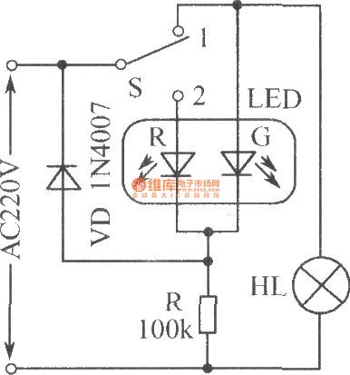
S is the 2-1 switch, when S is set to 1 bit, bulb HL gets electric and emits light, at the same time, th LED-G emits green light for the load working indiactor; HL is extinguished when S is set to 2 bit, LED-G is also turned off, only LED-R emits red light for the mains power indicator.
(View)
View full Circuit Diagram | Comments | Reading(1701)
Open circuit, short circuit anti-theft alarm
Published:2012/10/31 21:00:00 Author:Ecco | Keyword: Open circuit , short circuit , anti-theft alarm
It uses AC driver to make higher light power output by the light emitting diode, the driver circuit is shown in Figure. The two LEDs are connected reversely in parallel, so that the power's positive and negative half-cycle can be dispalyed by a light-emitting diode.
(View)
View full Circuit Diagram | Comments | Reading(1602)
10-point common-anode logarithmic display driver circuit using TA7612AP
Published:2012/10/31 21:04:00 Author:Ecco | Keyword: 10-point , common-anode, logarithmic display, driver
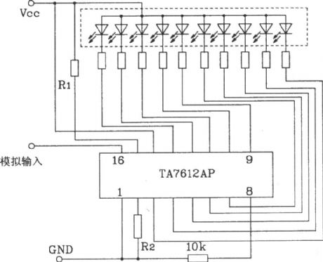
This circuit's input signal is an analog voltage input which is displayed on a logarithmic scale.
(View)
View full Circuit Diagram | Comments | Reading(1874)
ThinSOT Micropower Buck Regulator
Published:2012/10/30 22:30:00 Author:muriel | Keyword: ThinSOT, Micropower Buck Regulator
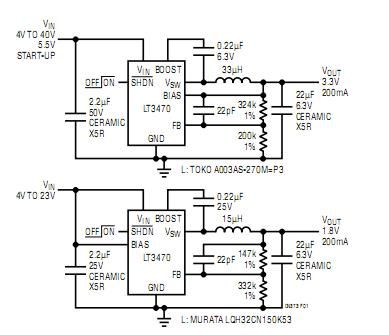
View full Circuit Diagram | Comments | Reading(805)
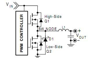
AN-6005 synchronous buck circuit
Published:2012/10/30 22:29:00 Author:muriel | Keyword: AN-6005, synchronous buck circuit
View full Circuit Diagram | Comments | Reading(885)
| Pages:284/2234 At 20281282283284285286287288289290291292293294295296297298299300Under 20 |
Circuit Categories
power supply circuit
Amplifier Circuit
Basic Circuit
LED and Light Circuit
Sensor Circuit
Signal Processing
Electrical Equipment Circuit
Control Circuit
Remote Control Circuit
A/D-D/A Converter Circuit
Audio Circuit
Measuring and Test Circuit
Communication Circuit
Computer-Related Circuit
555 Circuit
Automotive Circuit
Repairing Circuit