
Circuit Diagram
Index 289
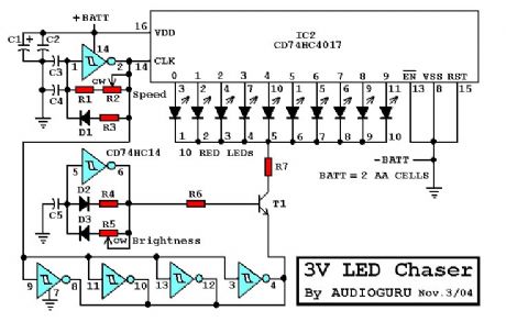
3-V led chaser
Published:2012/10/29 1:37:00 Author:muriel | Keyword: 3-V led chaser
View full Circuit Diagram | Comments | Reading(1895)
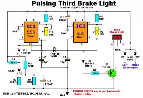
pulsing third brake light
Published:2012/10/29 1:36:00 Author:muriel | Keyword: pulsing , third brake light
View full Circuit Diagram | Comments | Reading(1692)
Rotating & Flashing 230V Lights
Published:2012/10/29 1:30:00 Author:muriel | Keyword: Rotating & Flashing, 230V, Lights
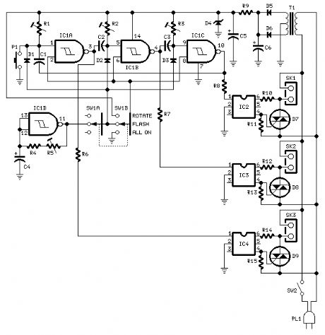
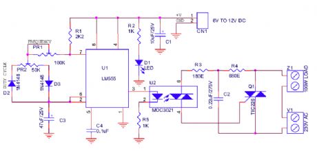
This design can be of some interest for those wanting striking light signs, as it can drive up to three 230V lamp strings in three operating modes.The 15V dc supply is obtained from a nominal 230/24V center tapped ac transformer (T1) and a full wave rectifier (D5 & D6): Zener diode D4 was added to clamp the dc voltage to 15V maximum.Triacs D7, D8 and D9 are insulated from the control circuitry by means of Optoisolators IC2, IC3 and IC4. IC1A, B and C are wired as monostables and cascaded in order to obtain a rotating sequence when the Mode switch SW1 is set in the Rotate position.IC1D acts as an astable multivibrator and generates an adjustable flashlight, driving all three lamp strings at the same time when the Mode switch SW1 is set in the Flash position.The All On operating mode allows all lamps to be on at the same time and can be used either for general illumination or to single out a blown bulb.Each channel can drive several 230V lamps wired in parallel for each string, provided the maximum current of the Triacs is not exceeded. For example, each channel will be able to drive up to 20 40W bulbs.The circuit is also well suited for many small bulbs wired in series like the usual Christmas tree lamp strings decorations. As these are very low power devices, a lot of them can be driven by this circuit. The more lamps per string are used, the more satisfactory will be the resulting effect. (View)
View full Circuit Diagram | Comments | Reading(1482)
220 Volts Flashing Lamps
Published:2012/10/29 1:30:00 Author:muriel | Keyword: 220 Volts , Flashing Lamps
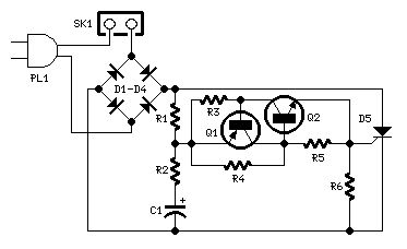
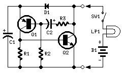
This circuit is intended as a reliable replacement to thermally-activated switches used for Christmas tree lamp-flashing. The device formed by Q1, Q2 and related resistors triggers the SCR. Timing is provided by R1,R2 & C1. To change flashing frequency don't modify R1 and R2 values: set C1 value from 100 to 2200µF instead.Best performances are obtained with C1=470 or 1000µF and R4=12K or 10K. Due to low consumption of normal 10 or 20 lamp series-loops intended for Christmas trees (60mA @ 220V typical for a 20 lamp series-loop), very small and cheap SCR devices can be used, e.g. C106D1 (400V 3.2A) or TICP106D (400V 2A), this last and the suggested P0102D devices having TO92 case. (View)
View full Circuit Diagram | Comments | Reading(1800)
200W Lamp Flasher
Published:2012/10/29 1:29:00 Author:muriel | Keyword: 200W, Lamp Flasher
View full Circuit Diagram | Comments | Reading(1878)
Two-wire Lamp Flasher
Published:2012/10/29 1:29:00 Author:muriel | Keyword: Two-wire , Lamp Flasher
View full Circuit Diagram | Comments | Reading(1340)
2 Transistor LED Flasher
Published:2012/10/29 1:28:00 Author:muriel | Keyword: 2 Transistor , LED Flasher
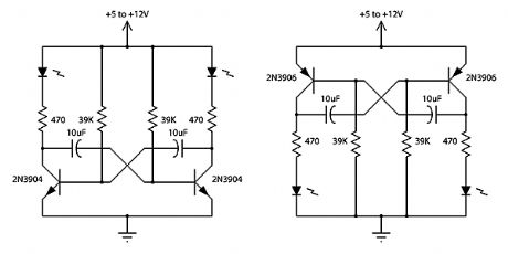
This is a classic 2 transistor astable multivibrator. Many other NPN small signal or switching transistors can be used, including 2N4401, PN2222 or 2N2222 using the circuit on the left. The circuit can also be inverted using PNP transistors such as 2N3906, 2N4403, PN2907, or 2N2907 as shown to the right. The 470 ohm resistors determine the LED brightness. Lower resistance means higher current, and more light. LEDs that require more current or have a higher operating voltage (such as green and yellow) may work better with 300 ohms. The RC time constant of the 39K ohms resistor and the 10uF capacitor determines the on time for each side. (The two sides do not need to match - vary the RC time constant for one side to get a lower or a higher duty cycle). With the values shown, the flash rate is about 1 cycle per second at 50% duty cycle.
(View)
View full Circuit Diagram | Comments | Reading(3303)
2 Transistor 2 LED Flasher
Published:2012/10/29 1:27:00 Author:muriel | Keyword: 2 Transistor , 2 LED Flasher
View full Circuit Diagram | Comments | Reading(2649)
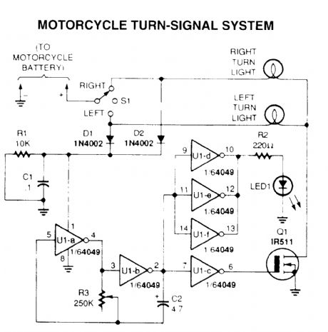
motorcycle turn-signal system
Published:2012/10/29 1:22:00 Author:muriel | Keyword: motorcycle turn-signal system
View full Circuit Diagram | Comments | Reading(2952)
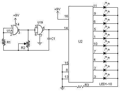
LED Chaser
Published:2012/10/29 1:14:00 Author:muriel | Keyword: LED Chaser
View full Circuit Diagram | Comments | Reading(1665)
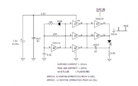
LED FLASHER NEEDS ONLY 1.5 VOLTS
Published:2012/10/29 1:13:00 Author:muriel | Keyword: LED FLASHER, 1.5 VOLTS
View full Circuit Diagram | Comments | Reading(1357)
1.5V LED Flasher Oscillator
Published:2012/10/29 1:12:00 Author:muriel | Keyword: 1.5V, LED Flasher Oscillator

View full Circuit Diagram | Comments | Reading(1228)
3v Low Battery Voltage Flasher Circuit
Published:2012/10/29 1:06:00 Author:muriel | Keyword: 3v , Low Battery Voltage, Flasher Circuit
View full Circuit Diagram | Comments | Reading(1272)
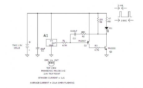
1.5V LED FLASHER VERSION B
Published:2012/10/29 1:06:00 Author:muriel | Keyword: 1.5V , LED FLASHER

View full Circuit Diagram | Comments | Reading(1872)
Digital Radar Speedometer
Published:2012/10/29 0:55:00 Author:muriel | Keyword: Digital Radar Speedometer
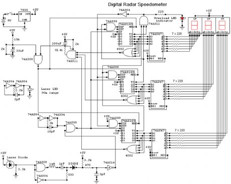
This circuit is a Digital Radar Speedometer. It allows us to evaluate the speed of any object moving, especially cars and other vehicles. The speed is calculated in kilometers per hour (KPH). Its display has three digits. This radar works with the laser reflexion. It sends laser radiation to the object and this object reflects the laser radiation to the radar. To evaluate the speed of a vehicle, we must be in front of it. In other words, the vehicle must come in our direction. The front of the radar must point the front of the vehicle. The radar has the shape of a pistol. In this radar, it has a laser LED and a laser diode. Both have a lens.
The laser LED can send a spot of light to a distance of 90 m (295 ft). It's very important that the distance range of the laser LED is 90 m, if not, the speed will not be calculated properly. The laser diode, which receives the light signal by the laser LED, must be able to detect the light which is same color as that emitted by the laser LED. The laser diode and the laser LED must be placed one beside the other. They are protected by a tinted pane. They must be placed at the front of the radar and point the outside. The radar is powered by a 9V battery and it has a SPST switch to control its power state.
The display, or the speed indicator, is placed at the rear of the radar, just on the right of the overload LED indicator. All the logic components of the circuit must be of the 74AS series and TTL type. Because they have short time of response (less than 1.7 ns) and have high frequency supports (more than 200 MHz). The radar can evaluate the speed of an object moving between 0 to 999 km/h. After this speed, the overload LED indicator will turn on and the 999 will still displayed. The radar displays the speed during 3 seconds, after this time, it displays zero (0). (View)
View full Circuit Diagram | Comments | Reading(2150)
Low-noise ac amplifier has digital control of gain and bandwidth
Published:2012/10/29 0:54:00 Author:muriel | Keyword: Low-noise ac amplifier
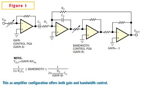
In low-noise analog circuits, a high-gain amplifier serves at the input to increase the SNR. The input signal level determines the input-stage gain; low-level signals require the highest gain. It is also standard practice in low-noise analog-signal processing to make the circuit's bandwidth as narrow as possible to pass only the useful input-signal spectrum. The optimum combination of an amplifier's gain and bandwidth is the goal of a low-noise design. In a data-acquisition system, digital control of gain and bandwidth provides dynamic adjustment to variations in input-signal level and spectrum. Figure 1 shows a simplified circuit for an ac amplifier with control of both gain and bandwidth. The amplifier's input is a PGA (programmable-gain amplifier) providing gain control (Gain A). Following the input PGA is a first-order highpass filter formed with capacitor C1 and input resistor R1 of an integrator circuit. Inside the integrator's feedback path, the gain of a second PGA (Gain B) multiplies the integrator's –3-dB frequency, thus providing bandwidth control. (View)
View full Circuit Diagram | Comments | Reading(1940)
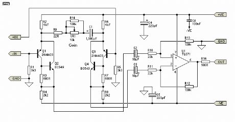
Low Noise Microphone Preamplifier
Published:2012/10/29 0:53:00 Author:muriel | Keyword: Low Noise, Microphone Preamplifier
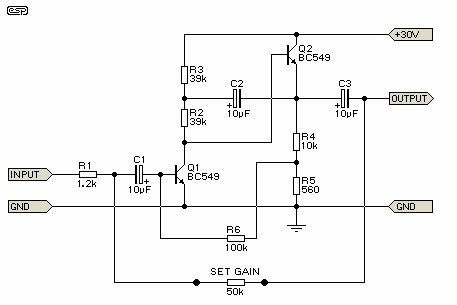
This is a design for a low noise microphone preamplifier, which is ideally suited to low impedance (600 Ohm nominal) microphones. One limitation is that it is not balanced, which is not a problem in a home recording environment, but will allow the mic lead (and case) to pick up noise with long cable runs or in a hostile environment.
As shown, it is not really suitable for professional work (although it has been used on stage in its unbalanced form with good results), but the addition of a 1:1 microphone transformer on the input will convert it into a balanced preamp with very high performance. In many cases, a transformer will actually outperform active balancing circuits, because there is (or should be) no ground reference. The shield of the balanced cable must be earthed of course, but in my experience with live music and studio work, less noise is picked up if the internal wiring is floating.
It is most regrettable that good mic transformers are rather hard to come by, and are expensive. If you happen to have a suitable one in your junk box, give it a try with this circuit - I doubt that you will be disappointed with the result. I have used this circuit in Front-of-House, foldback (monitor) and studio mixers, and managed to obtain excellent results - I still have a little 6 channel mixer (which I use only occasionally now) using this circuit, and have never been even slightly tempted to replace it with even the best of opamps (or Figure 3 for that matter). (View)
View full Circuit Diagram | Comments | Reading(4619)
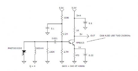
medium power 40kHz light receiver amp
Published:2012/10/29 0:52:00 Author:muriel | Keyword: medium power , 40kHz , light receiver amp
View full Circuit Diagram | Comments | Reading(877)
Low Noise Balanced Microphone Preamp
Published:2012/10/29 0:51:00 Author:muriel | Keyword: Low Noise, Balanced Microphone Preamp
The input stage is configured for least noise and this has meant a non IC approach. There are some special ICs that can be used for mic pre-amps, they contain a circuit like this one except fabricated on one chip. Examples include the SSM2017 (now obsolete) or the replacement INA103 or similar.
Components should all be readily available except for the 10 k ohm pot for the gain control. This needs to be a reverse log taper - or else use a multi-position switch with 6 dB gain steps covering the 60 dB range of the circuit. Make sure it is make before break.
Editor's Note - Alternatively, a standard log pot can be used, but wired backwards . This will work fine if it is labelled Attenuation instead of Gain . As the pot is advanced clockwise, the gain is reduced (attenuation is increased). Maximum gain will therefore be applied when the pot is fully anti-clockwise. Note that this is not a problem that is specific to this circuit - all the IC mic preamps have exactly the same problem. (View)
View full Circuit Diagram | Comments | Reading(3473)
LOW acoustic-optical siren circuit
Published:2012/10/28 21:02:00 Author:Ecco | Keyword: LOW , acoustic-optical siren
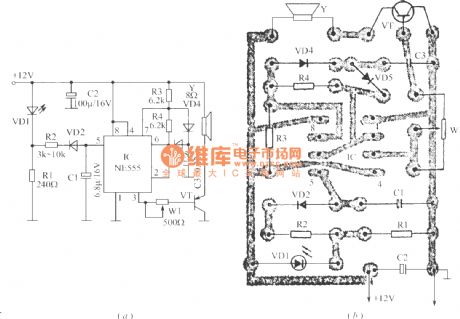
The circuit can generate high intensity warning sound, and it can be used as anti - theft siren. When power alarm system is connected, VD1 flashes and eimts light, R1 resistor outputs pulse square wave which is converted into triangle wave after passing R2, VD2 and C1 network, IC is a 555 time-base circuit to form a voltage-controlled oscillator. R3, R4 and C3 are timing elements. Under the control of the triangular wave, the output variable tone signals is amplified by VT to promote speakers, and its output power closes to l0W. Adjusting R1 can change the amplitude of the triangle wave on C1, and adjusting W1 can change the volume. Figure (b) is a printed circuit board installation diagram.
(View)
View full Circuit Diagram | Comments | Reading(1263)
| Pages:289/2234 At 20281282283284285286287288289290291292293294295296297298299300Under 20 |
Circuit Categories
power supply circuit
Amplifier Circuit
Basic Circuit
LED and Light Circuit
Sensor Circuit
Signal Processing
Electrical Equipment Circuit
Control Circuit
Remote Control Circuit
A/D-D/A Converter Circuit
Audio Circuit
Measuring and Test Circuit
Communication Circuit
Computer-Related Circuit
555 Circuit
Automotive Circuit
Repairing Circuit