
Circuit Diagram
Index 296
120 VAC Lamp Dimmer
Published:2012/10/22 21:59:00 Author:muriel | Keyword: 120 VAC , Lamp Dimmer
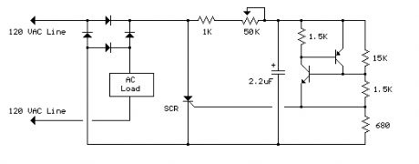
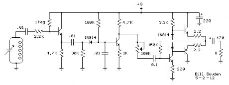
The full wave phase control circuit below was found in a RCA power circuits book from 1969. The load is placed in series with the AC line and the four diodes provide a full wave rectified voltage to the anode of a SCR. Two small signal transistors are connected in a switch configuration so that when the voltage on the 2.2uF capacitor reaches about 8 volts, the transistors will switch on and discharge the capacitor through the SCR gate causing it to begin conducting. The time delay from the beginning of each half cycle to the point where the SCR switches on is controlled by the 50K resistor which adjusts the time required for the 2uF capacitor to charge to 8 volts. As the resistance is reduced, the time is reduced and the SCR will conduct earlier during each half cycle which applies a greater average voltage across the load. With the resistance set to minimum the SCR will trigger when the voltage rises to about 40 volts or 15 degrees into the cycle. To compensate for component tollerances, the 15K resistor can be adjusted slightly so that the output voltage is near zero when the 50K pot is set to maximum. Increasing the 15K resistor will reduce the setting of the 50K pot for minimum output and visa versa. Be careful not to touch the circuit while it is connected to the AC line. (View)
View full Circuit Diagram | Comments | Reading(1359)
DC to DC Converter
Published:2012/10/22 21:58:00 Author:muriel | Keyword: DC to DC, Converter
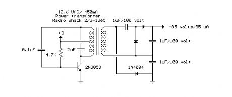
The circuit below is a DC to DC converter using a standard 12 VAC center tapped power transformer wired as a blocking oscillator. The circuit is not very efficient but will produce a high voltage usable for low power applications. The input battery voltage is raised by a factor of 10 across the transformer and further raised by a voltage tripler consisting of three capacitors and diodes connected to the high voltage side of the transformer. The circuit draws about 40 milliamps and should operate for about 200 hours on a couple of 'D' alkaline batteries. Higher voltages can be obtained by reducing the 4.7K bias resistor. (View)
View full Circuit Diagram | Comments | Reading(2253)
Whistle On - Whistle Off
Published:2012/10/22 21:57:00 Author:muriel | Keyword: Whistle On , Whistle Off
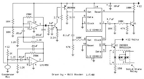
This is an extension of the CMOS toggle flip flop circuit shown in the Circuits controlling relays section with the addition of two bandpass filters and condenser microphone so the relay can be toggled by whistling at it. The condender mic used is a PC board mount Radio Shack #270-090C. The filters are tuned to about 1700 Hz, or the third Ab above middle C on a piano keyboard which is a fairly easy note for me to whistle. Resistor values for the filter can be computed using the three formulas below but we need to assume a gain and Q factor for the filter and the Q of the circuit must be greater than the square root of (Gain/2). The microphone produces only a couple millivolts so the overall gain needs to be around 4000 or around 65 for each filter. The Q or quality factor is the ratio of the center frequency to the bandwidth (-3dB points) and was chosen to be 8 which is greater than 5.7 which is the minimum value for a gain of 65. Both capacitor values need to be the same for easy computation of the resistor values and were chosen to be 0.01uF which is a common value and usable at audio frequencies. From those assumptions, the resistor values can be worked out from the following formulas. (View)
View full Circuit Diagram | Comments | Reading(909)
2 Watt Switching Power Supply
Published:2012/10/22 21:57:00 Author:muriel | Keyword: 2 Watt , Switching Power Supply
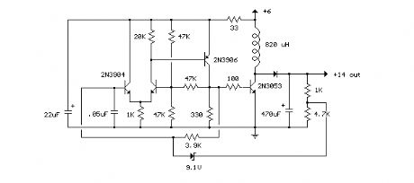
In this small switching power supply, a Schmitt trigger oscillator is used to drive a switching transistor that supplies current to a small inductor. Energy is stored in the inductor while the transistor is on, and released into the load circuit when the transistor switches off. The output voltage is dependent on the load resistance and is limited by a zener diode that stops the oscillator when the voltage reaches about 14 volts. Higher or lower voltages can be obtained by adjusting the voltage divider that feeds the zener diode. The efficiency is about 80% using a high Q inductor. (View)
View full Circuit Diagram | Comments | Reading(1096)
Variable Voltage and Current Power Supply
Published:2012/10/22 21:56:00 Author:muriel | Keyword: Variable Voltage , Current, Power Supply
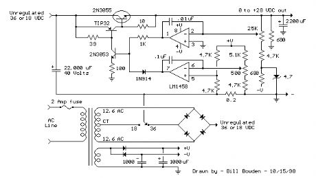
Another method of using opamps to regulate a power supply is shown below. The power transformer requires an additional winding to supply the op-amps with a bipolar voltage (+/- 8 volts), and the negative voltage is also used to generate a reference voltage below ground so that the output voltage can be adjusted all the way down to 0. Current limiting is accomplished by sensing the voltage drop across a small resistor placed in series with the negative supply line. As the current increases, the voltage at the wiper of the 500 ohm pot rises until it becomes equal or slightly more positive than the voltage at the (+) input of the opamp. The opamp output then moves negative and reduces the voltage at the base of the 2N3053 transistor which in turn reduces the current to the 2N3055 pass transistor so that the current stays at a constant level even if the supply is shorted. Current limiting range is about 0 - 3 amps with components shown. The TIP32 and 2N3055 pass transistors should be mounted on suitable heat sinks and the 0.2 ohm current sensing resistor should be rated at 2 watts or more. The heat produced by the pass transistor will be the product of the difference in voltage between the input and output, and the load current. So, for example if the input voltage (at the collector of the pass transistor) is 25 and the output is adjusted for 6 volts and the load is drawing 1 amp, the heat dissipated by the pass transistor would be (25-6) * 1 = 19 watts. In the circuit below, the switch could be set to the 18 volt position to reduce the heat generated to about 12 watts. (View)
View full Circuit Diagram | Comments | Reading(1960)
Variable 3 - 24 Volt / 3 Amp Power Supply
Published:2012/10/22 21:56:00 Author:muriel | Keyword: Variable, 3 - 24 Volt, 3 Amp , Power Supply
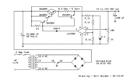
This regulated power supply can be adjusted from 3 to 25 volts and is current limited to 2 amps as shown, but may be increased to 3 amps or more by selecting a smaller current sense resistor (0.3 ohm). The 2N3055 and 2N3053 transistors should be mounted on suitable heat sinks and the current sense resistor should be rated at 3 watts or more. Voltage regulation is controlled by 1/2 of a 1558 or 1458 op-amp. The 1458 may be substituted in the circuit below, but it is recommended the supply voltage to pin 8 be limited to 30 VDC, which can be accomplished by adding a 6.2 volt zener or 5.1 K resistor in series with pin 8. The maximum DC supply voltage for the 1458 and 1558 is 36 and 44 respectively. The power transformer should be capable of the desired current while maintaining an input voltage at least 4 volts higher than the desired output, but not exceeding the maximum supply voltage of the op-amp under minimal load conditions. The power transformer shown is a center tapped 25.2 volt AC / 2 amp unit that will provide regulated outputs of 24 volts at 0.7 amps, 15 volts at 2 amps, or 6 volts at 3 amps. The 3 amp output is obtained using the center tap of the transformer with the switch in the 18 volt position. All components should be available at Radio Shack with the exception of the 1558 op-amp.
(View)
View full Circuit Diagram | Comments | Reading(1530)
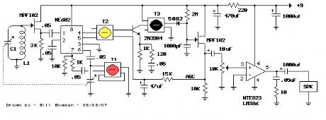
AM Radio Receiver With Additional IF Stage
Published:2012/10/22 21:55:00 Author:muriel | Keyword: AM Radio Receiver, Additional IF Stage
Pictured above is the same circuit with an additional IF stage added forgreater sensitivity. Overall gain can be adjusted with the 1K resistorsin the emitter leg of the 2N3904 transistors. The circuit board was assembledusing multiturn 10K pots in place of the 1K resistors and then adjusted forbest performance. The pots are the 2 little blue items just to the left ofthe tuning cap. I think I ended up with about 750 ohms. The emitter bypasscaps are not needed since there is plenty of gain available without them.The caps (two yellow items near the pots) are still in the board but notconnected. I didn't know if they were needed or not, so I put them in thereanyway and later disconnected them. Removing the bypass caps also increasesthe input impedance so that both IF stages can use the black IF coils whichhave higher secondary impedances (and thus more voltage) than the yellow orwhite coils. You might be able to replace the yellow coil with a black onefor greater signal transfer since the input to the first transistor is muchhigher without the bypass cap, but I didn't try it. You may notice one of theblack coils is actually white in the picture but it was rewound for a highersecondary impedance. Actually, it was removed from a junk radio purchased fora dollar and didn't have any secondary, so I added a 27 turn secondary whichis close to what the black coils use. Overall, the performance is very goodexcept for the AGC circuit, which has limited range and may not be ableto compensate for very strong stations which may overload the circuit.The AGC voltage is derived from the IF amplitude at the cathode of thedetector diode (output of T4). As the IF amplitude increases, the DCvoltage at the gate of the JFET will move negative, below ground.The audio signal is present on both the gate and source terminals of theJFET, but the audio DC offset voltage will change as the IF amplitudechanges. This DC voltage (about 2 volts) is fed back through a 15K resistorand the two IF coil secondaries to control the transistor bias points.The audio signal is filtered out by the 47uF cap leaving a stable DCvoltage at the base of the transistors. As the base voltage drops, theemitter voltages also drop resulting in less operating current and lowergain for two IF stages. But the range is limited to maybe only 6-12dBwhich isn't enough to compensate for very strong signals. One solutionto the problem is a manual gain control consisting of a switch anda few turns of wire around the antenna coil which can be seen in thepicture (3 turns of solid insulated white wire on left side of loopstick).Closing the switch loads the antenna coil and reduces the signal level. (View)
View full Circuit Diagram | Comments | Reading(2810)
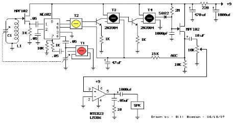
AM Radio Receiver Using the NE602 Balanced Mixer
Published:2012/10/22 21:54:00 Author:muriel | Keyword: AM Radio Receiver, NE602 , Balanced Mixer
Pictured above is a little AM superhetrodyne receiver that covers thebroadcast band from 550 Khz to 1650 Khz. The circuit employs the 8 pinSignetics balanced mixer IC (NE602) which converts the incoming RF signalto the standard 455 Khz IF signal and provides about 13dB gain. The IFsignal is amplified by a single transistor stage and audio is recoveredusing a biased shotkey diode (5082) and JFET buffer transistor. The LM386audio amp is used to drive a small 2.5 inch speaker at about 200 milliwatts.The circuit contains four LC tuned circuits, all of which need to be finetuned to obtain good results. An oscilloscope and RF signal generator areuseful, but the circuit can also be setup using local radio stationsand an additional portable AM radio. (View)
View full Circuit Diagram | Comments | Reading(6551)
TRF AM Broadcast Receiver Using a Loop Antenna
Published:2012/10/22 21:53:00 Author:muriel | Keyword: TRF AM Broadcast, Receiver, Loop Antenna
The TRF radio above operates on the AM broadcast band in the range of 550-1650 Khz.It's similar to a crystal radio with the addition of a couple buffer stages andaudio amp to drive a speaker. Reception is limited to strong local stations. KFI(Los Angeles) comes in loud and clear at a range of about 7 miles from the 50KWstation. KNX (1070) and KLAC (570) can be heard at low levels and a few otherstations can be barely heard if I put my ear against the speaker. The receiver usesa 16 inch square loop antenna wound on a wooden frame (13 turns #18) with a variable(30-365pF) capacitor. Larger loops would probably work better. Also, performancemight be better if the loop is rotated 45 degrees, so the frame looks like across (+) instead of an X. That way, the top and bottom sides will not be parallelto the ground, and the antenna will have more height.The antenna signal is buffered by the first emitter follower stage which presentsabout 150K input impedance. The buffer stage avoids losing much voltage from theantenna when connected to the circuit. The buffered RF voltage at the emitter ofthe transistor is rectified by the diode, and the RF component removed by thecapacitor at the base of the second transistor. This leaves only the audio signalat the base with about 5X higher amplitude at the collector. The 3 remainingtransistors form an audio amp to drive the 8 ohm speaker. The transistors usedare 2N3906 (PNP) and 2N4123 (NPN) however 2N3904 should work as well. The 100Kvariable resistor shown is only used to reduce the volume of very strong stations,such as KFI in my case. The speaker is a 4 inch model with a heavy 4 inch magnetinside a 6 inch box. Seems to be more efficient than speakers with smaller magnets.Headphones work better and I can hear 8 stations in the Los Angeles area at lowvolume. The complete circuit draws about 10mA from a 9 volt battery. (View)
View full Circuit Diagram | Comments | Reading(1954)
Quartz Crystal Synchronizer for Pendulum Windup Wall Clock
Published:2012/10/22 21:51:00 Author:muriel | Keyword: Quartz Crystal Synchronizer, Pendulum Windup, Wall Clock
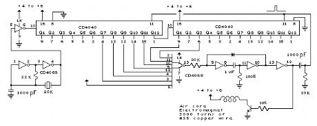
Mechanical Clock Project:Last year, I found a 31 day pendulum wall clock (dissambled) in a box ofparts at a swap meet and decided to try and put it together and regulateit with a quartz crystal oscillator. The escapement part that rocks backand forth and drives the pendulum was missing and had to be made froma couple razor blade pieces and heavy copper wire. The razor blade escapementworked well but only allowed the movement to advance as the pendulum swung,and would not sustain the pendulum motion by itself. But this wasn't aproblem since the quartz crystal divider circuit provides energy to thependulum with an electromagnet to keep it swinging with only a 5 seconderror per day. The 31 day mainspring was included, but I wanted to use aweight and drive wheel in place of the spring.The clock movement is made in Korea by Sau Jin LTD Dae Woo CO LTD and has no jewels. It measures 4.5 inches diameter by 1.5 inchesdeep plus 1.5 inches for the hands and drive wheel shafts, so the clockface and hands are about 3 inches from the wall. The pendulum periodis close to 53.4 complete swings per minute. Can't figure out why thatparticular period was used. I have seen similar movements on ebay.The clock pendulum was made using a 10 inch, 3/16 wooden dowel with astrong magnet attached to the bottom and a small weight near the topto adjust the period close to 53 beats per minute. The circuit boardand electromagnet to drive the pendulum are located on a small shelf(not shown) and positioned so the pendulum magnet swings close to thestationary electromagnet and receives a small pulse on each swing tosustain oscillation. The pulse duration is about 5% of the pendulumperiod and a LED is used to indicate the pulse output. The clock startsfairly easily by releasing the pendulum near the magnet when theLED flash is observed. (View)
View full Circuit Diagram | Comments | Reading(1497)
Light Level Indicator Using a Window Comparator
Published:2012/10/22 21:50:00 Author:muriel | Keyword: Light Level , Indicator, Window Comparator
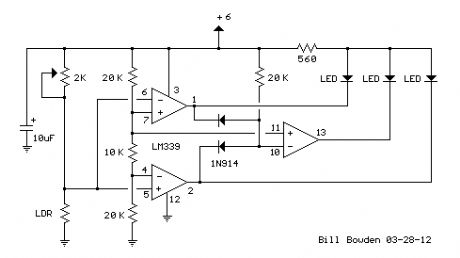
The second example below uses a LDR (light dependent resistor) to indicatesome desired light level. The LDR has a large dynimic range and varies inresistance from less than 100 ohms on a cloudy day to over a megohm in totaldarkness. A 2K pot was used to adjust the window range for usual room lightconditions. This setup might also be used to indicate sunrise/sunset conditions. (View)
View full Circuit Diagram | Comments | Reading(1717)
Temperature Range Indicator Using a Window Comparator
Published:2012/10/22 21:49:00 Author:muriel | Keyword: Temperature Range , Indicator, Window Comparator
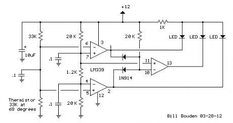
A window comparator usually employs 2 comparators with one output indicatingthe input is somewhere between two limits. In these examples, a thirdcomparator is added to display all three conditions where the input is inthe center range, or higher, or lower.The first example uses a thermistor to indicate the temperature is near68 degrees within about +/- 5 degree tollerance. The thermistor measures33K at around 68 degrees and varies about 3570 ohms over a range of 10 degrees.Using a 12 volt supply, the thermistor voltage will be 6 volts in the centerof the range. As the temperature increases 10 degrees, the total resistancefalls 3750 ohms, the current will be 12/ (66K -3750) =193uA and the thermistorvoltage will be 193u * (33k -3750) = 5.65 volts. This represents a voltagechange of (6 - 5.65) = 350 millivolts for a 10 degree change. The center resistorof the window voltage divider must then drop 350 millivolts. Using 20K resistorson the top and bottom of the window voltage divider produces a current of(6 - (.350/2)) / 20K = 291uA, and the center resistor is .350/291u = 1.2KWhen the temperature is in the center of the window range, the voltage atpins 5 and 6 will be 1/2 the supply voltage, or 6 volts in this case.The voltage divider (20K, 1.2K, 20K) produces a voltage of around 5.8 atpin 4 and 6.2 at pin 7. Since the voltage at pin 5 (6 volts) is more positivethan the voltage at pin 4 (5.8 volts), the output at pin 2 will be a highlevel. At the same time, the voltage at pin 7 (+ input) is higher thanpin 6 (- input) causing pin 1 to also be a high level. This conditionproduces a high (12 volt) level at pin 10 (- input) which produces a lowlevel at pin 13, lighting the window LED indicating the temperature is inthe window range. As the thermistor voltage moves above the upper 6.2 limit,pin 1 will switch low, extinguishing the window LED and illuminating the(Low Temp) LED. Similar action happens as the thermistor voltage moves belowthe lower 5.8 limit causing pin 2 to switch low (Over Temp LED) while theother two LEDs remain off. (View)
View full Circuit Diagram | Comments | Reading(2046)
Photo Electric Street Light
Published:2012/10/22 21:48:00 Author:muriel | Keyword: Photo, Electric, Street Light
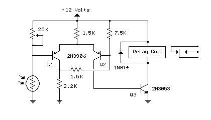
This is basically a Schmitt Trigger circuit which receives input from a cadmium sulfide photo cell and controls a relay that can be used to switch off and on a street lamp at dawn and dusk. I have built the circuit with a 120 ohm/12 volt relay and monitored performance using a lamp dimmer, but did not connect the relay to an outside light.
The photo cell should be shielded from the lamp to prevent feedback and is usually mounted above the light on top of a reflector and pointed upward at the sky so the lamp light does not strike the photo cell and switch off the lamp.
The photo cell is wired in series with a potentiometer so the voltage at the junction (and base of transistor) can be adjusted to about half the supply, at the desired ambient light level. The two PNP transistors are connected with a common emitter resistor for positive feedback so as one transistor turns on, the other will turn off, and visa versa. Under dark conditions, the photo cell resistance will be higher than the potentiometer producing a voltage at Q1 that is higher than the base voltage at Q2 which causes Q2 to conduct and activate the relay.
The switching points are about 8 volts and 4 volts using the resistor values shown but could be brought closer together by using a lower value for the 7.5K resistor. 3.3K would move the levels to about 3.5 and 5.5 for a range of 2 volts instead of 4 so the relay turns on and off closer to the same ambient light level. The potentiometer would need to be readjusted so that the voltage is around 4.5 at the desired ambient condition.
(View)
View full Circuit Diagram | Comments | Reading(1431)
LED Traffic Lights
Published:2012/10/22 21:47:00 Author:muriel | Keyword: LED, Traffic Lights
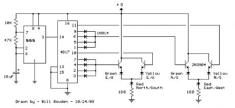
The LED traffic Light circuit controls 6 LEDs (red, yellow and green) for both north/south directions and east/west directions. The timing sequence is generated using a CMOS 4017 decade counter and a 555 timer. Counter outputs 1 through 4 are wire ORed using 4 diodes so that the (Red - North/South) and (Green - East/West) LEDs will be on during the first four counts. The fifth count (pin 10) illuminates (Yellow - East/West) and (Red - North/South). Counts 6 through 9 are also wire ORed using diodes to control (Red - East/West) and (Green - North/South). Count 10 (pin 11) controls (Red - East/West) and (Yellow - North/South). The time period for the red and green lamps will be 4 times longer than for the yellow and the complete cycle time can be adjusted with the 47K resistor. The eight 1N914 diodes could be subsituted with a dual 4 input OR gate (CD4072). (View)
View full Circuit Diagram | Comments | Reading(1955)
Line Powered White LEDs
Published:2012/10/22 21:46:00 Author:muriel | Keyword: Line Powered , White LEDs
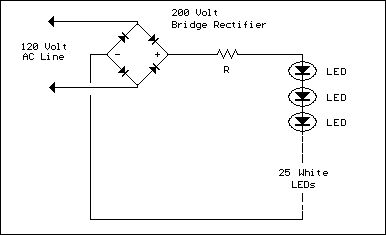
The LED circuit below is an example of using 25 white LEDs in series connected to the 120VAC line. It can be modified for more or less LEDs by adjusting the resistor value. The exact resistance will depend on the particular LEDs used. But working out the resistor value is a bit complicated since current will not continously flow through the resistor.
In operation, the output of the bridge rectifier will be about 120 DC RMS or 170 volts peak. If we use 25 white LEDs with a forward voltage of 3 volts each, the total LED voltage will be 75 volts. The peak resistor voltage will be 170- 75 or 95 volts but the resistor voltage will not be continous since the input must rise above 75 before any current flows. This (dead time) represents about 26 degrees of the 90 degree half wave rectified cycle, (asin) 75/170 = (asin) .44 = 26 degrees. This means the resistor will conduct during 90-26 = 64 degrees, or about 71 percent of the time.
Next we can work out the peak LED current to determine the resistor value. If the LED current is 20mA RMS, the peak current will be 20*1.414 or 28mA. But since the duty cycle is only 71 percent, we need to adjust this figure up to 28/0.71 = 39mA. So, the resistor value should be 95/.039 = 2436 ohms (2.4K) and the power rating will be .02^2 *2400= .96 watts. A two watt size is recommended.
Now this circuit can also be built using 2 diodes and resistor as shown in the lower drawing. The second diode in parallel with the LEDs is used to avoid a reverse voltage on the LEDs in case the other diode leaks a little bit. It may not be necessary but I thought it was a good idea.
Working out the resistor value is similar to the other example and comes out to about half the value of the full wave version, or about 1.2K at 1 watt in this case. But the peak LED current will be twice as much or about 78mA. This is probably not too much, but you may want to look up the maximum current for short duty cycles for the LEDs used and insure 79mA doesn't exceed the spec. (View)
View full Circuit Diagram | Comments | Reading(1817)
AC Line powered LEDs
Published:2012/10/22 21:46:00 Author:muriel | Keyword: AC Line, powered LEDs
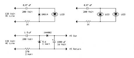
The circuit below illustrates powering a LED (or two) from the 120 volt AC line using a capacitor to drop the voltage and a small resistor to limit the inrush current. Since the capacitor must pass current in both directions, a small diode is connected in parallel with the LED to provide a path for the negative half cycle and also to limit the reverse voltage across the LED. A second LED with the polarity reversed may be subsituted for the diode, or a tri-color LED could be used which would appear orange with alternating current. The circuit is fairly efficient and draws only about a half watt from the line. The resistor value (1K / half watt) was chosen to limit the worst case inrush current to about 150 mA which will drop to less than 30 mA in a millisecond as the capacitor charges. This appears to be a safe value, I have switched the circuit on and off many times without damage to the LED. The 0.47 uF capacitor has a reactance of 5600 ohms at 60 cycles so the LED current is about 20 mA half wave, or 10 mA average. A larger capacitor will increase the current and a smaller one will reduce it. The capacitor must be a non-polarized type with a voltage rating of 200 volts or more.
The lower circuit is an example of obtaining a low regulated voltage from the AC line. The zener diode serves as a regulator and also provides a path for the negative half cycle current when it conducts in the forward direction. In this example the output voltage is about 5 volts and will provide over 30 milliamps with about 300 millivolts of ripple. Use caution when operating any circuits connected directly to the AC line. (View)
View full Circuit Diagram | Comments | Reading(2261)
1.5 Volt LED Flashers
Published:2012/10/22 21:45:00 Author:muriel | Keyword: 1.5 Volt, LED Flashers
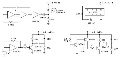
The LED flasher circuits below operate on a single 1.5 volt battery. The circuit on the upper right uses the popular LM3909 LED flasher IC and requires only a timing capacitor and LED.
The top left circuit, designed by Andre De-Guerin illustrates using a 100uF capacitor to double the battery voltage to obtain 3 volts for the LED. Two sections of a 74HC04 hex inverter are used as a squarewave oscillator that establishes the flash rate while a third section is used as a buffer that charges the capacitor in series with a 470 ohm resistor while the buffer output is at +1.5 volts. When the buffer output switches to ground (zero volts) the charged capacitor is placed in series with the LED and the battery which supplies enough voltage to illuminate the LED. The LED current is approximately 3 mA, so a high brightness LED is recommended.
In the other two circuits, the same voltage doubling principle is used with the addition of a transistor to allow the capacitor to discharge faster and supply a greater current (about 40 mA peak). A larger capacitor (1000uF) in series with a 33 ohm resistor would increase the flash duration to about 50mS. The discrete 3 transistor circuit at the lower right would need a resistor (about 5K) in series with the 1uF capacitor to widen the pulse width. (View)
View full Circuit Diagram | Comments | Reading(1350)
Generating -5 Volts From a 9 Volt Battery
Published:2012/10/22 21:44:00 Author:muriel | Keyword: Generating, -5 Volts, 9 Volt, Battery
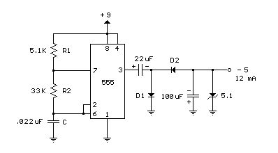
A 555 timer can be used to generate a squarewave to produce a negative voltage relative to the negative battery terminal. When the timer output at pin 3 goes positive, the series 22 uF capacitor charges through the diode (D1) to about 8 volts. When the output switches to ground, the 22 uF cap discharges through the second diode (D2) and charges the 100 uF capacitor to a negative voltage. The negative voltage can rise over several cycles to about -7 volts but is limited by the 5.1 volt zener diode which serves as a regulator. Circuit draws about 6 milliamps from the battery without the zener diode connected and about 18 milliamps connected. Output current available for the load is about 12 milliamps. An additional 5.1 volt zener and 330 ohm resistor could be used to regulate the +9 down to +5 at 12 mA if a symmetrical +/- 5 volt supply is needed. The battery drain would then be around 30 mA. (View)
View full Circuit Diagram | Comments | Reading(1094)
555 Tone Generator (8 ohm speaker)
Published:2012/10/22 21:43:00 Author:muriel | Keyword: 555 , Tone Generator, 8 ohm speaker
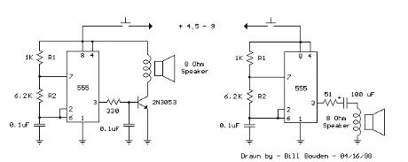
This is a basic 555 squarewave oscillator used to produce a 1 Khz tone from an 8 ohm speaker. In the circuit on the left, the speaker is isolated from the oscillator by the NPN medium power transistor which also provides more current than can be obtained directly from the 555 (limit = 200 mA). A small capacitor is used at the transistor base to slow the switching times which reduces the inductive voltage produced by the speaker. Frequency is about 1.44/(R1 + 2*R2)C where R1 (1K) is much smaller than R2 (6.2K) to produce a near squarewave. Lower frequencies can be obtained by increasing the 6.2K value, higher frequencies will probably require a smaller capacitor as R1 cannot be reduced much below 1K. Lower volume levels can be obtained by adding a small resistor in series with the speaker (10-100 ohms). In the circuit on the right, the speaker is directly driven from the 555 timer output. The series capacitor (100 uF) increases the output by supplying an AC current to the speaker and driving it in both directions rather than just a pulsating DC current which would be the case without the capacitor. The 51 ohm resistor limits the current to less than 200 mA to prevent overloading the timer output at 9 volts. At 4.5 volts, a smaller resistor can be used. (View)
View full Circuit Diagram | Comments | Reading(1212)
Inductive proximity switch circuit
Published:2012/10/21 20:30:00 Author:Ecco | Keyword: Inductive, proximity switch
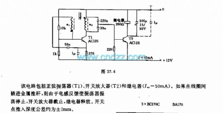
The circuit includes a sinusoidal oscillator (T1), switching amplifier (T2) and relay (Im = 50mA). If metal plunger is inserted into the coils, the inductance feedback will make the oscillator oscillation stop, the switching amplifier is turned off, then the relay releases. The switch point push depth tolerance is approximately ± 2mm.
(View)
View full Circuit Diagram | Comments | Reading(4209)
| Pages:296/2234 At 20281282283284285286287288289290291292293294295296297298299300Under 20 |
Circuit Categories
power supply circuit
Amplifier Circuit
Basic Circuit
LED and Light Circuit
Sensor Circuit
Signal Processing
Electrical Equipment Circuit
Control Circuit
Remote Control Circuit
A/D-D/A Converter Circuit
Audio Circuit
Measuring and Test Circuit
Communication Circuit
Computer-Related Circuit
555 Circuit
Automotive Circuit
Repairing Circuit