
Circuit Diagram
Index 291
Alarm circuit diagram using op amp
Published:2012/10/25 21:29:00 Author:Ecco | Keyword: Alarm , op amp
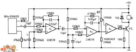
A1 and A2 form the two-stage amplifier which can amplifer output signal of pyroelectric sensor IRA-E006SX to a desired level. A3 is a comparator, and RP adds reference voltage to the inverting input terminal of A3, whe A2 output level is higher than the reference voltage, A3 outputs a high level to make VT1 conduction, relay κ action to drive the alarm.
(View)
View full Circuit Diagram | Comments | Reading(1338)
The alarm circuit diagram using DS-505 pyroelectric sensor
Published:2012/10/25 21:26:00 Author:Ecco | Keyword: alarm , pyroelectric sensor
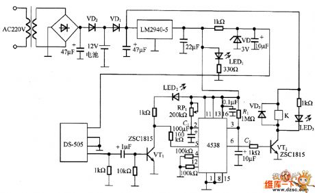
In the circuit, DS-505 receives the infrared radiation from human body and turned it into a voltage signal, then it is amplified by VT1 and added pin 5 of 4538 ( B - side) to start timer, then the pin 6 ( Q side) outputs high level, and VT2 gets conduction to drive relay K action its contacts are connected to the alarm device alarm. In the circuit, the timing time is determined by the time constant of RP1 and C1, R1 and C2 are used to prevent the erroneous operation of the timer when the power is turned on , LED1, LED2 and LED3 respectively show the power supply, sensor output and the operation of the relay.
(View)
View full Circuit Diagram | Comments | Reading(1977)
AC power monitor circuit diagram
Published:2012/10/25 21:12:00 Author:Ecco | Keyword: AC power monitor
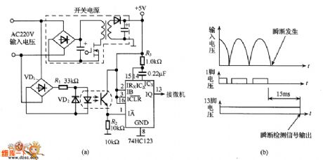
When AC power is suddenly turned off becauseof lightning strikes and other reasons, the important data stored in computer may disappear, so it needs to add short interruption power detection circuit to protect the memory data. AC220V voltage is rectified and regulated to get +5 V output voltage which is used as the working power of computer, but also working power of timer 74HC123. 74HC123's pin 13 is connected to the microcomputer. When AC power is normal, the 74HC123 timer resets, then output is in high level, computer works properly. When the AC power is anomaly, detection AC power occurs short interruptions with 15ms, then 74HC123's pin 13 output changes from the high to low level, then the computer will do data preservation work.
(View)
View full Circuit Diagram | Comments | Reading(3212)
Sensor and Relay Circuits
Published:2012/10/25 21:29:00 Author:muriel | Keyword: Sensor , Relay Circuits
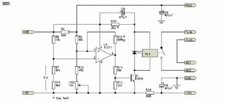
In Figure, I have shown the reed relay connections, together with an efficiency circuit (R13 & C4), that will reduce the holding current to the bare minimum. C4 is used to provide an initial full voltage to the relay coil, to ensure that it will pull in reliably. After C4 is charged, the only current flows through R13, and the current is just sufficient to keep the relay energised, so current drain is minimised. You may need to adjust the value of R13 depending on the relays used - as shown, it is suitable for a 12V reed relay with a coil resistance of around 1k ohm, and limits holding current to approximately 7.5mA. R16 is optional but recommended. It ensures that switching is clean , with no relay chattering. The series combination of R7 and R15 can be replaced with a single 51k resistor if preferred.
The sensor works by detecting the voltage dropped across the sense resistor. When current is drawn, a small voltage is developed across the resistor (R8), and this is used to switch the opamp from a normally high output state to a voltage of about 2V. This switches off Q1, which in turn de-activates the relay and disconnects the charger. When the external circuit is switched off, the voltage across the sense resistor falls to near zero, the opamp changes output state, and the relays are energised, thus reconnecting the charger.
The charger must be able to supply enough current to keep the relays energised, as well as provide power to charge the batteries (and power U1 - typically about 2.5mA), so minimising relay current is important.
If you switch the power to your external equipment on-off-on-off quickly, you may find that the relay does not re-activate after the last power-off. This can happen if C4 is charged, and has not had time to discharge fully, so the relay coil doesn't get the pulse needed to close the contacts. The easy way to prevent this is not to switch on and off rapidly. (View)
View full Circuit Diagram | Comments | Reading(2012)
Automatic Charger for Battery Operated Hi-Fi Preamps
Published:2012/10/25 21:28:00 Author:muriel | Keyword: Automatic Charger , Battery Operated Hi-Fi Preamps
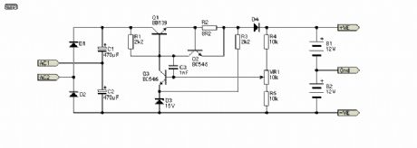
The charger is shown in Figure, and is a conventional (but very simple) regulator. A 3-terminal regulator is not suitable for this, as the voltage across it will be too high if the batteries are discharged. The charger uses a standard 15V transformer (which connects to the terminals marked ~In, Fig. 2), and uses a voltage doubler to provide a nominal 40V supply for the charger.
R1 provides current limiting so that heavily discharged batteries will not be damaged, nor damage the charger due to excessive current. Remember that Ni-Cd cells in particular should be charged at 0.1 x capacity - a 1AH (Ampere-Hour) cell should be charged at a maximum of 100mA (0.1 x 1).
As shown, the maximum current is limited to about 90mA - low enough for nearly all cells likely to be used for powering preamps and such. VR1 is used to set the float voltage, and this should be done as accurately as possible - a 10 turn pot is highly recommended to enable you to get an accurate setting. At 90mA, and with deeply discharged batteries, the dissipation in Q1 will be rather high - worst case is a little over 2 Watts, and a heatsink is essential. Should more current be needed, this is easily done by reducing the value of R2 - half the value will give double the current and vice versa. It is important that you ensure that the heatsink for Q1 is sufficient for the expected load current. C1 and C2 must be rated at a minimum of 50V - not because of the voltage, but to obtain a sufficiently high ripple current rating, especially when the charger is in current limit mode. (View)
View full Circuit Diagram | Comments | Reading(1351)
STMicroelectronics battery charger ICs
Published:2012/10/25 21:25:00 Author:muriel | Keyword: STMicroelectronics, battery charger ICs
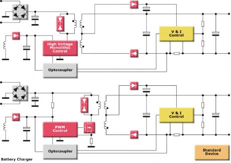
STMicroelectronics provides battery charger ICs and full solutions for cell phones, note books, digital cameras, hand tools and many other battery-powered applications. Several solutions are proposed to charge lithium-ion, nickel-metal hydride and nickel-cadmium batteries. Switched mode solutions are mainly used in portable or high power applications. The following block diagram shows a wide range of productsfor battery charger designs.
(View)
View full Circuit Diagram | Comments | Reading(1250)
Solar Cell Phone Charger circuits
Published:2012/10/25 21:17:00 Author:muriel | Keyword: Solar Cell, Phone Charger circuits
View full Circuit Diagram | Comments | Reading(1277)
Atmel Solar Panel Battery Charger
Published:2012/10/25 21:16:00 Author:muriel | Keyword: Atmel , Solar Panel, Battery Charger
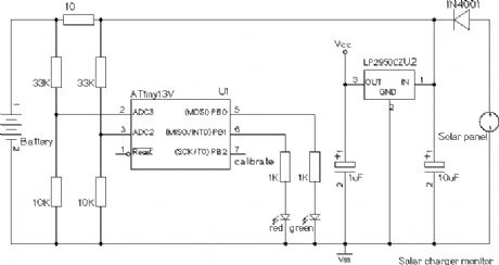
Batwatch is a simple monitor for a solar panel battery charger, using an Atmel ATtiny13V. It periodically measures the charge current and battery voltage, and shows them by blinking two LEDs. I built this circuit into the plug of a VW solar charger panel that is used to prevent a discharge of the battery when a car is not used for some time. A modern car contains a large amount of electronics, and a quiescent current of 40-50mA (about 1Ah per day!) is considered normal .
Every couple of seconds, the software samples the two analog inputs, calculates the charge current and battery voltage, and shows the voltage on the red LED and the charge current on the green LED. The voltage is shown in units of 0.1V using three decimal digits, and the current is shown in units of 10mA using two decimal digits. Each digit is represented by a number of short flashes corresponding to the value of the digit. A zero is represented by a single longer flash. When the charge current is below 10mA (after rounding) or negative, the green LED is not turned on at all. I use 4 times oversampling to get an 11-bit result, following the technique described in the Atmel application note AVR121. I'm not sure if there is enough noise on the inputs to actually increase the resolution, but it will not hurt either. The raw A/D reading is converted to a voltage using a separate pair of offset/gain constants for each input. These constants are derived from the calibration data stored in the EEPROM. To save power, all delays are implemented by executing one or more sleep instructions which cause the CPU to idle until the next timer interrupt. The interrupt frequency is 100 Hz, so each sleep pauses up to 10 mS.
(View)
View full Circuit Diagram | Comments | Reading(1903)
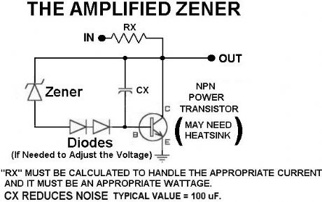
An Amplified Zener
Published:2012/10/25 21:15:00 Author:muriel | Keyword: An Amplified Zener
View full Circuit Diagram | Comments | Reading(1381)
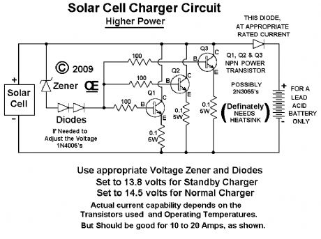
high power Solar Cell Battery Chargers
Published:2012/10/25 21:14:00 Author:muriel | Keyword: high power, Solar Cell, Battery Chargers
View full Circuit Diagram | Comments | Reading(2774)
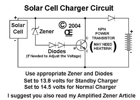
Solar Cell Battery Chargers
Published:2012/10/25 21:13:00 Author:muriel | Keyword: Solar Cell, Battery Chargers
View full Circuit Diagram | Comments | Reading(1705)
Low Current Power Supply Circuit
Published:2012/10/25 21:12:00 Author:muriel | Keyword: Low Current, Power Supply Circuit
View full Circuit Diagram | Comments | Reading(795)
Automatic Solar Power Supply Circuit
Published:2012/10/25 21:09:00 Author:muriel | Keyword: Automatic Solar, Power Supply Circuit
View full Circuit Diagram | Comments | Reading(1310)
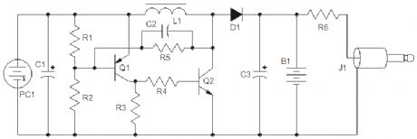
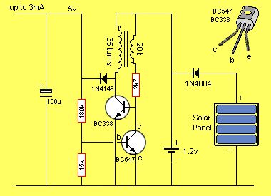
5v SOLAR POWER SUPPLY
Published:2012/10/25 21:07:00 Author:muriel | Keyword: 5v , SOLAR POWER SUPPLY
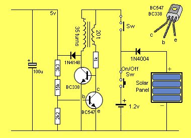
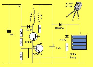
The circuit consists of an oscillator transistor and a regulator transistor. The solar panel charges the battery when sunlight is bright enough to produce a voltage above 1.9v. A diode is required between the panel and the battery as it leaks about 1mA from the battery when it is not illuminated.The regulator transistor is designed to limit the output voltage to 5v. This voltage will be maintained over the capability of the circuit, which is about 10mA. The oscillator transistor must be a high-current type as is is turned on for a very short period of time to saturate the core of the transformer.This energy is then released as a high-voltage pulse. (View)
View full Circuit Diagram | Comments | Reading(1456)
12V, 4-AA Cell Differential Temperature Charger
Published:2012/10/25 21:06:00 Author:muriel | Keyword: 12V, 4-AA , Cell Differential Temperature, Charger
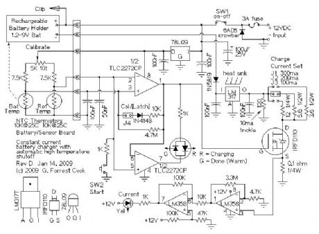
12VDC power is supplied to the circuit from an external source such as a car battery system, a 12V solar power system or a regulated wall wart supply. If DC power is applied backwards, the 6A05 crowbar diode causes the 3A fuse to blow, protecting the circuit from reverse voltage. The power switch routes power to the 78L09 voltage regulator and the battery. The 78L09 regulator provides regulated power to the rest of the circuit.
The battery current loop starts with the +12V supply, then runs through the battery and through a 1N5819 reverse voltage protection diode. Current continues through the LM317 1 amp adjustable voltage regulator which is wired as a constant current source, through the IRFD110 power MOSFET transistor, which switches charging current on and off, through the 0.1 ohm current sensing resistor to ground (12VDC negative). The charge current is selected by jumpering one of three current-set resistors on the negative side of the LM317 regulator. The 120 ohm trickle charge resistor always allows 10mA of current to flow through the battery.
The temperature control part of the circuit starts with a matched pair of 10K NTC thermistors. One thermistor is epoxied to a small metal reference temperature plate. The other thermistor is epoxied to a metal battery holder. The temperature sensors are balanced by the calibrate potentiometer. The 100nF and 50nF capacitors across the thermistors cause different start-up time delays to insure that the following circuitry powers up in the off state.
The upper half of the TLC2272CP rail-to-rail op-amp is wired as a latching comparator when the Cal/Latch jumper is present (operate mode), the circuit becomes a regular comparator with hysteresis when the jumper is off (calibrate mode). Assuming the battery is cold and the circuit is in operate mode, the start switch turns the op-amp on for a charging cycle. When the battery temperature exceeds the reference temperature, the op-amp turns off and the diode in the feedback loop latches the op-amp off. The op-amp output also drives the IRFD110 current switch MOSFET.
The lower half of the TLC2272CP simply inverts the output from the upper part of the op-amp, this gives a bipolar drive signal for running the Red/Green Charging/Done light.
An optional current flow lamp was added to the circuit. Rechargeable batteries tend to get corroded contacts which can prevent the charging current from flowing. The lamp provides an indication that the charging current is really making its way through the batteries. The current Flow lamp circuit consists of an LM358 op-amp wired as a current measurement amplifier that monitors the voltage drop across a 0.1 ohm resistor. The LM358 is specially suited for this type of circuit. The output of the first LM358 stage is further boosted and offset by the second LM358 stage. This produces a digital signal that drives the indicator LED through a current limiting resistor. If you don't want to add the Current Flow circuit, replace the 0.1 ohm resistor with a wire jumper. (View)
View full Circuit Diagram | Comments | Reading(1907)
12V input, 12V battery charger
Published:2012/10/25 21:04:00 Author:muriel | Keyword: 12V input, 12V , battery charger
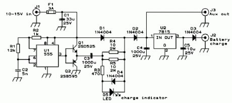
Some of you might wonder why a charger is needed at all, to charge a 12 Volt battery from a 12 Volt source! Well, firstly the 12 Volt source will typically vary anywhere from 11 Volt to 15 Volt, and then a battery needs acontrolled charge current and voltage, which cannot result from connecting it directly to a voltage source.
The charger described here is intended for charging small 12 Volt lead acid batteries, such as the gelled or AGM batteries of capacities between about 2 and 10 Ah, using a car's electrical system as power source, regardless of whether the car engine is running or not.
I built this charger many years ago, I think I was still in school back then. On request of a reader of my web site, I'm publishing it now, despite being a rather crude circuit. It works, it is uncritical to build, and uses only easy-to-find parts, so it has something in its favor. The downside is mainly the low efficiency: This charger wastes about as much power as it puts into the battery.
(View)
View full Circuit Diagram | Comments | Reading(2137)
12 VOLT GEL CELL CHARGER
Published:2012/10/25 21:02:00 Author:muriel | Keyword: 12 VOLT , GEL CELL CHARGER
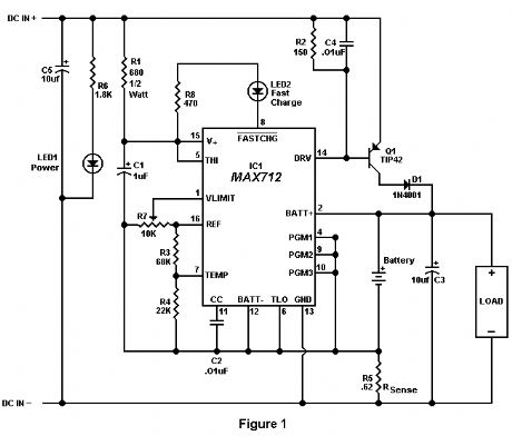
Recently, a fellow amateur was looking for a gel cell charger which would first charge at a fixed rate and then later switch to a trickle charge when the cell was fully charged. After reviewing several catalogs and web sites, the MAX712 IC was discovered. This IC meets all the requirements for almost any type of battery charging system. The circuit in Figure 1 was designed specifically for 12 volt gel cells.
When a discharged gel cell is connected, the charger goes into a fast charge mode at a fixed rate of 400 ma. After the chip detects the voltage leveling off or when 4 1/2 hours has elapsed. (which ever happens first.) the fast charge will stop. After the fast charge has ended, the IC goes into a trickle charge rate of about 50 ma. This trickle charge continues until 13.8 volts is reached which will stop all charging current since the cell is now fully charged. If the cell voltage should drop for any reason, either a fast charge or trickle charge (IC will detect what is needed) will start again.
When constructing this circuit, be sure to attach a small heat sink to Q1. Apply a DC (partially filtered) voltage of at least 15.3 volts. The voltage must never go below this level even under load conditions. Many of the DC wall transformers available will work just fine as long as they meet the minimum voltage requirement. The input voltage can be as high as 24 volts. If the input voltage must be in the 30 volt range, increase R1 to about 820 ohms.
The output voltage must be aligned prior to use. Disconnect the battery from the circuit and apply power. Connect a digital volt meter or other accurate volt meter to pin 2 (positive lead) and to pin 12 (negative lead). Adjust R7 until exactly 13.8 volts is read.
Because this circuit will not overcharge a gel cell, the battery can be connected indefinitely. This circuit is designed primarily as a 12 backup system and can be connected to the load provided the device to be powered only draws current during power line interruptions. Use a diode from the battery to load if needed. This circuit makes an excellent battery backup to an amateur transceiver.
The MAX712 IC and the .62 ohm resistor are available from Digi-Key, 701 Brooks Ave, Thief River Falls, MN 56701 (1-800-344-4539). Order part numbers MAX712CPE-ND and 0.62W-1-ND respectively. All other parts are available at Radio Shack. (View)
View full Circuit Diagram | Comments | Reading(1621)
1.3 Volt Power Source
Published:2012/10/25 21:01:00 Author:muriel | Keyword: 1.3 Volt , Power Source
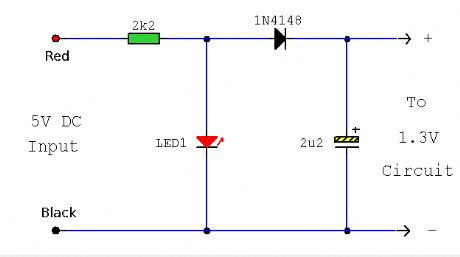
This is a replacement power source for 1.3V mercury cells or other small batteries. It has many uses and I use this circuit in my computer to power a front panel multi adapter which has a digital thermometer.This circuit takes it power from a PC. The power connectors have colour coded wiring, red and black are the 5V supply, black and yellow are the 12V supply. These are extremely high current so absolute care must be taken to avoid short circuits and an inline fuse of 100mA is recommended. The 1.3V is derived from a Red LED. When on and forward biased the LED's voltage drop between anode and cathode is about 1.9V, this is too high for mercury cell powered equipment, but fed in series with a 1N4148 signal diode drops around 0.6V, the supply is then ideal to drive battery powered peripherals.This is not suitable for clocks, because when the computer is turned off the 5V supply is also switched off. It is however ideal for the independent temperature displays often included with PC preripherals such as case mounted usb connectors. (View)
View full Circuit Diagram | Comments | Reading(1119)
Two 12v Battery Isolator Circuit with a LTC4412
Published:2012/10/25 21:00:00 Author:muriel | Keyword: Two 12v , Battery Isolator Circuit, LTC4412
View full Circuit Diagram | Comments | Reading(2673)
Solar Powered Cell Phone Charger
Published:2012/10/25 20:59:00 Author:muriel | Keyword: Solar Powered , Cell Phone, Charger
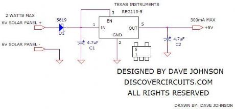
The simple circuit below regulates the voltage from a 6v solar panel to a fixed +5v. That voltage can be fed to any cell phone or USB connected portable device, to charge its battery. The circuit uses a Reg113-5 voltage regulator from Texas Instruments. The tiny device can handle up to 400ma of charging current. I would suggest using a solar panel rated for less than 2 watts and one which contains 12 solar cells. One such panel is shown below. (View)
View full Circuit Diagram | Comments | Reading(3890)
| Pages:291/2234 At 20281282283284285286287288289290291292293294295296297298299300Under 20 |
Circuit Categories
power supply circuit
Amplifier Circuit
Basic Circuit
LED and Light Circuit
Sensor Circuit
Signal Processing
Electrical Equipment Circuit
Control Circuit
Remote Control Circuit
A/D-D/A Converter Circuit
Audio Circuit
Measuring and Test Circuit
Communication Circuit
Computer-Related Circuit
555 Circuit
Automotive Circuit
Repairing Circuit