
Circuit Diagram
Index 288
advertising badge flasher
Published:2012/10/29 21:47:00 Author:muriel | Keyword: advertising badge flasher

View full Circuit Diagram | Comments | Reading(1128)
FLASHING LED ADVERTISING BADGE #2
Published:2012/10/29 21:46:00 Author:muriel | Keyword: FLASHING LED , ADVERTISING BADGE
View full Circuit Diagram | Comments | Reading(1080)
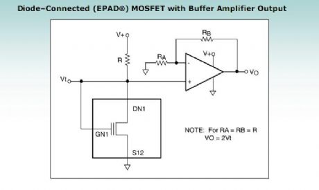
diode-connected MOSFET with buffer amplifier output
Published:2012/10/29 21:45:00 Author:muriel | Keyword: diode-connected MOSFET , buffer amplifier output

View full Circuit Diagram | Comments | Reading(1359)
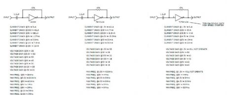
CMOS Logic Inverter Amplifier
Published:2012/10/29 21:44:00 Author:muriel | Keyword: CMOS, Logic Inverter Amplifier
View full Circuit Diagram | Comments | Reading(1178)
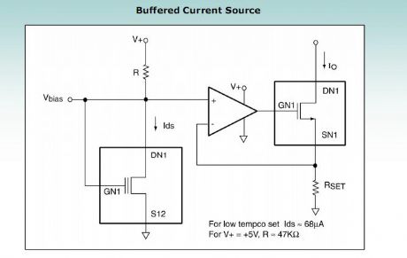
buffered current source
Published:2012/10/29 21:43:00 Author:muriel | Keyword: buffered current source
View full Circuit Diagram | Comments | Reading(906)
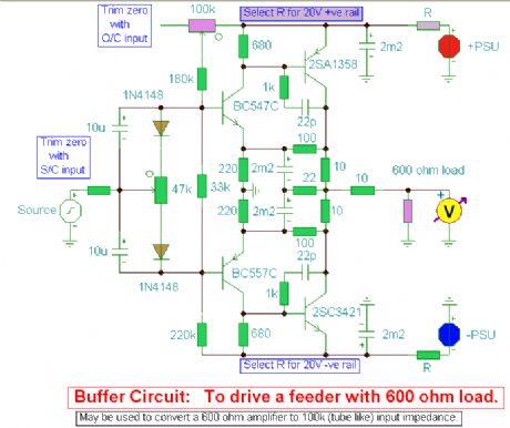
Buffer Amplifier circuit
Published:2012/10/29 21:42:00 Author:muriel | Keyword: Buffer Amplifier circuit
View full Circuit Diagram | Comments | Reading(1697)
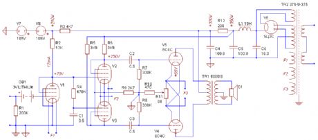
All-directly-Heated Pushpull Amp
Published:2012/10/29 21:41:00 Author:muriel | Keyword: All-directly-Heated, Pushpull Amp
View full Circuit Diagram | Comments | Reading(1070)
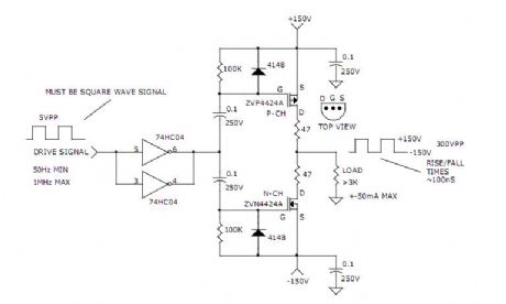
300V PEAK TO PEAK SIGNAL GENERATOR
Published:2012/10/29 21:39:00 Author:muriel | Keyword: 300V , PEAK TO PEAK , SIGNAL GENERATOR
View full Circuit Diagram | Comments | Reading(1152)
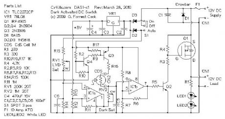
DAS1 - 12 Volt 10 Amp Dark Activated Switch
Published:2012/10/29 21:36:00 Author:muriel | Keyword: DAS1 - 12 Volt, 10 Amp, Dark Activated Switch
View full Circuit Diagram | Comments | Reading(1143)
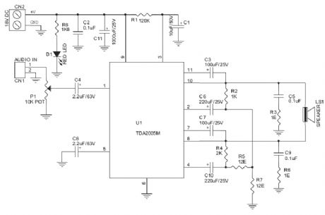
20-W Bridge Audio Amplifier
Published:2012/10/29 1:48:00 Author:muriel | Keyword: 20-W , Bridge Audio Amplifier
View full Circuit Diagram | Comments | Reading(1088)
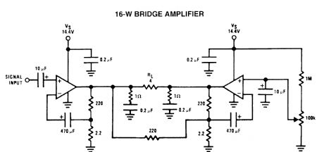
16-W bridge amplifier circuits
Published:2012/10/29 1:47:00 Author:muriel | Keyword: 16-W, bridge amplifier circuits
View full Circuit Diagram | Comments | Reading(1792)
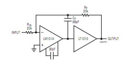
Practical LT1010 Based Boosted Op Amp
Published:2012/10/29 1:45:00 Author:muriel | Keyword: Practical LT1010, Based Boosted , Op Amp
View full Circuit Diagram | Comments | Reading(1226)
Highpass filters
Published:2012/10/29 1:44:00 Author:muriel | Keyword: Highpass filters
View full Circuit Diagram | Comments | Reading(781)
A simple step-up converter (6V to 12V)
Published:2012/10/29 1:43:00 Author:muriel | Keyword: A simple step-up converter, 6V to 12V
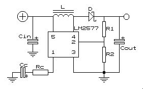
This step-up converter is intended for use in a '67 Citroen 2CV. This car, and I use the word loosely, has a 6V battery and won't support a modern radio that needs 12V. The circuit described here converts 6V to 12V at 1A sustained load current.
When the switch is closed an extra current flows through the inductance and stores energy there. The capacitor supplies the load with current during this time.
After the switch closes the capacitor is charged by the energy stored in the inductance and an extra current starts flowing through the load, causing the output voltage to rise (energy is supplied directly from the input source also as long as the diode is forward biased). During this time, the system behaves like a RLC-circuit, so, after a while, the current decreases. The switch is then closed again and the cycle repeats. One could say that charge is pumped from input to output, increasing the output voltage up to the point where there is an equilibrium between the discharging of the capacitor while the switch is closed and the charging by the inductor while the switch is open.
The output voltage equals (ton / toff + 1)ΧUin and is controlled by PWM of the switching action. (View)
View full Circuit Diagram | Comments | Reading(1890)
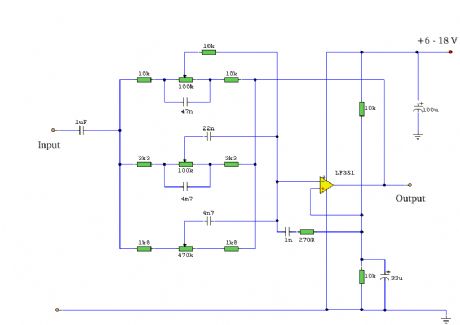
3-Band Equalizer
Published:2012/10/29 1:42:00 Author:muriel | Keyword: 3-Band Equalizer
View full Circuit Diagram | Comments | Reading(0)
Two Transistor (Boy's Radio) Schematic and Theory of Operation
Published:2012/10/29 1:41:00 Author:muriel | Keyword: Two Transistor
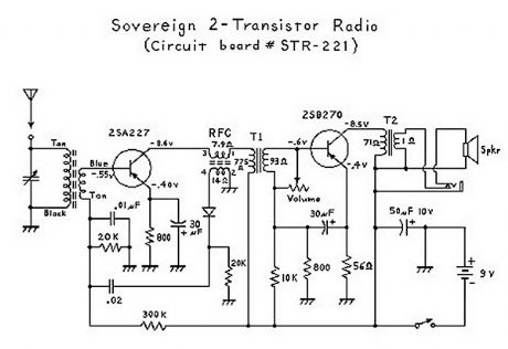
It has been interesting analyzing these radios. You have to give the Japanese credit for even making a radio that can drive a speaker with only 2 transistors! Basically, the first transistor (Q1) performs double-duty. It first acts as an RF amplifier, with some of the signal being fed back to the antenna coil to provide some regeneration for better selectivity and sensitivity. (This also results in a non-linear amplification of the signal which results in noticeable distortion.) The RF (radio frequency) signal is then rectified ( detected ) by the diode, and then the resultant audio signal is fed back to the base of the first transistor where it acts as the first AF (audio frequency) amplifier. (This is called a reflex circuit.) The audio signal is then fed through an interstage transformer to Q2 (the second transistor). The transformer provides impedance matching. The second transistor acts as a power amplifier, with the output signal going through an audio output transformer (to provide impedance matching again), and then finally to the speaker. Everything about this circuit is designed to provide maximimum gain; consequently there is no AGC (automatic gain control), and stronger stations come in a lot louder than weaker stations; unlike 6-transistor (or more) radio circuits which have an AGC circuit or function. (View)
View full Circuit Diagram | Comments | Reading(7642)
12V to 28V DC-DC Converter with LM2585
Published:2012/10/29 1:40:00 Author:muriel | Keyword: 12V to 28V, DC-DC Converter, LM2585
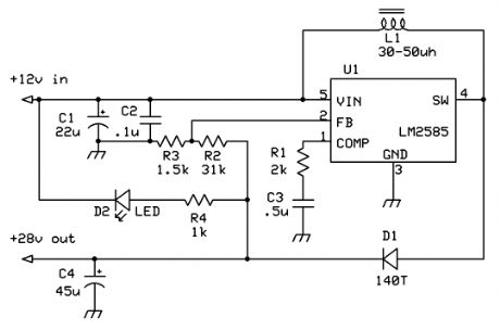
This boost regulator is for those times when you have a 28v relay, but want to use it with a 12v source. The circuit is built around the National Semiconductor LM2585, and uses the energy stored in an inductor to boost the 12v to 28. Output voltage can be varied by adjusting the ratio of resistor values on the feedback pin. (View)
View full Circuit Diagram | Comments | Reading(1600)
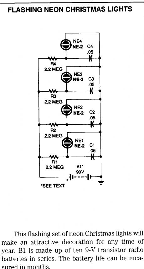
flashing neon charistmas lights
Published:2012/10/29 1:39:00 Author:muriel | Keyword: flashing, neon , charistmas lights
View full Circuit Diagram | Comments | Reading(1557)
8 Random Flashing Leds Circuit
Published:2012/10/29 1:39:00 Author:muriel | Keyword: 8 Random, Flashing Leds Circuit
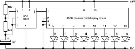
This project flashes eight LEDs in an apparently random manner. It uses a 4060 combined counter and display driver IC which is designed for driving 7-segment LED displays. The sequence is not really random because seven of the LEDs would normally be the display segments, the eighth LED is driven by an output that is normally used for driving further counters. The table below shows the sequence for the LEDs. You can use less than eight LEDs if you wish and the table may help you decide which ones to use for your purpose. (View)
View full Circuit Diagram | Comments | Reading(2749)
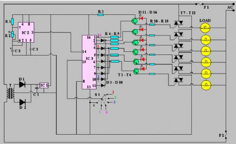
6 Channel Auto Reverse Sequential Disco Running Lights
Published:2012/10/29 1:38:00 Author:muriel | Keyword: 6 Channel, Auto Reverse Sequential, Disco Running Lights
View full Circuit Diagram | Comments | Reading(4859)
| Pages:288/2234 At 20281282283284285286287288289290291292293294295296297298299300Under 20 |
Circuit Categories
power supply circuit
Amplifier Circuit
Basic Circuit
LED and Light Circuit
Sensor Circuit
Signal Processing
Electrical Equipment Circuit
Control Circuit
Remote Control Circuit
A/D-D/A Converter Circuit
Audio Circuit
Measuring and Test Circuit
Communication Circuit
Computer-Related Circuit
555 Circuit
Automotive Circuit
Repairing Circuit