
Circuit Diagram
Index 297
Gas smoke alarm circuit
Published:2012/10/21 20:41:00 Author:Ecco | Keyword: Gas smoke alarm
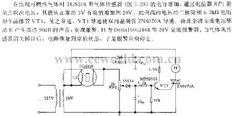
TGS308 gas sensor conductance ( Figure 5.18 ) increases in the event of combustible gas, and the voltage is got by the potentiometer RP1 slide point, and its value is increased from normal 3V rms to 20V, this elevated voltage is added to transistor VT1 by diode and 4.7kΩ resistor, so that it gets conduction, VT1 conduction makes Triacs 2N6070A get conduction. Thus, full-wave AC voltage can drive E to produce up to 90dB alarm sound. H is Deltal6003168 type 24V AC alarm. When gas disappears from the sensor, the circuit is restored to the original state, so the alarm automatically stops.
(View)
View full Circuit Diagram | Comments | Reading(1017)
Frequency selective photoelectric relay circuit
Published:2012/10/21 22:51:00 Author:Ecco | Keyword: Frequency selective , photoelectric relay
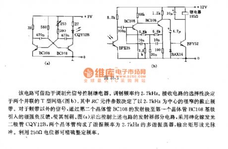
The circuit can use modulated optical signal to control the relay. The modulation frequency is approximately 2.7kHz, and the selectivity of receiving circuit is determined by two parallel T-network. The parameters of RC elements decide narrow stopband with 2.7kHz center. Figure a shows controlling the circuit for transmitter portion of the circuit, and it uses a GaAs light emitting diode CQY12B, and two transistors constitute a multivibrator with 2.7kHz resonant frequency, and it outputs the rectangular wave pulse. It uses 250Ω potentiometer to accurately tune frequency.
(View)
View full Circuit Diagram | Comments | Reading(1240)
Colorful circulation lantern control circuit associated with the Music Box Dance
Published:2012/10/22 2:34:00 Author:Ecco | Keyword: Colorful circulation lantern , control , Music Box Dance
It consists of a time-base pulse generator, count / divider circuit, SCR trigger control lantern circuit, songs sound circuit and AC buck rectifier circuit and other components. It will set red, green, blue three primary colors of light in a matte shade, according to the principle of three primary colors, it can control the count frequency circuit, then the tricolor lights automatically display the red, blue, green, purple, blue, yellow, white seven colors in a rolling cycle. At the same time, it also issues a beautiful music box dance. The circuit uses fewer components with low cost, and it can be used for advertising lights, ballroom lights, family Dream lamps and supplier cupboard decorative lights. The circuit uses AC buck rectifier power supply.
(View)
View full Circuit Diagram | Comments | Reading(1086)
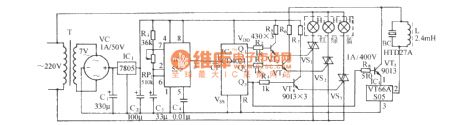
Three-way Kala 0K lighting rendering circuit (HL3033)
Published:2012/10/22 2:42:00 Author:Ecco | Keyword: Three-way, Kala 0K, lighting rendering

As shown in the figure, it is a Kala 0K lighting rendering controller with audio voltage controlled ASIC HL3033 produced by Wuxi love Silicon microelectronics company. It has a three-way outputs, the flowing speed of the light will change with the loudness of concert, and it can powerfully render concert atmosphere and beautify the indoor environment, so it is very suitable for home Kala 0K concert.
(View)
View full Circuit Diagram | Comments | Reading(1120)
Thermostat for 1KW Space Heater (SCR controlled)
Published:2012/10/22 1:30:00 Author:muriel | Keyword: Thermostat, 1KW, Space Heater , SCR controlled
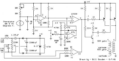
Below is a thermostat circuit I recently built to control a 1300 watt space heater. The heater element (not shown) is connected in series with two back to back 16 amp SCRs (not shown) which are controlled with a small pulse transformer. The pulse transformer has 3 identical windings, two of which are used to supply trigger pulses to the SCRs, and the third winding is connected to a PNP transistor pair that alternately supply pulses to the transformer at the beginning of each AC half cycle. The trigger pulses are applied to both SCRs near the beginning of each AC half cycle but only one conducts depending on the AC polarity.
DC power for the circuit is shown in the lower left section of the drawing and uses a 1.25uF, 400 volt non-polarized capacitor to obtain about 50mA of current from the AC line. The current is rectified by 2 diodes and used to charge a couple larger low voltage capacitors (3300uF) which provide about 6 volts DC for the circuit. The DC voltage is regulated by the 6.2 volt zener and the 150 ohm resistor in series with the line limits the surge current when power is first applied.
The lower comparator (output at pin 13) serves as a zero crossing detector and produces a 60 Hz square wave in phase with the AC line. The phase is shifted slightly by the 0.33 uF, 220K and 1K network so that the SCR trigger pulse arrives when the line voltage is a few volts above or below zero. The SCRs will not trigger at exactly zero since there will be no voltage to maintain conduction.
The upper two comparators operate in same manner as described in the Electronic thermostat and relay circuit. A low level at pin 2 is produced when the temperature is above the desired level and inhibits the square wave at pin 13 and prevents triggering of the SCRs. When the temperature drops below the desired level, pin 2 will move to an open circuit condition allowing the square wave at pin 13 to trigger the SCRs.
The comparator near the center of the drawing (pins 8,9,14) is used to allow the heater to be manually run for a few minutes and automatically shut off. A momentary toggle switch (shown connected to a 51 ohm resistor) is used to discharge the 1000uF capacitor so that pin 2 of the upper comparator moves to a open circuit state allowing the 60 Hz square wave to trigger the SCRs and power the heater. When the capacitor reaches about 4 volts the circuit returns to normal operation where the thermistor controls the operation. The momentary switch can also be toggled so that the capacitor charges above 4 volts and shuts off the heater if the temperature is above the setting of the pot. (View)
View full Circuit Diagram | Comments | Reading(1800)
Electronic Thermostat and Relay Circuit
Published:2012/10/22 1:30:00 Author:muriel | Keyword: Electronic Thermostat, Relay Circuit
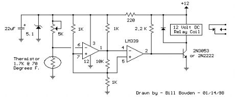
Here is a simple thermostat circuit that can be used to control a relay and supply power to a small space heater through the relay contacts. The relay contacts should be rated above the current requirements for the heater. Temperature changes are detected by a (1.7K @ 70F) thermistor placed in series with a 5K potentiometer which produces about 50 millivolts per degree F at the input of the LM339 voltage comparator. The two 1K resistors connected to pin 7 set the reference voltage at half the supply voltage and the hysteresis range to about 3 degrees or 150 millivolts. The hysteresis range (temperature range where the relay engages and disengages) can be adjusted with the 10K resistor between pins 1 and 7. A higher value will narrow the range. In operation, the series resistor is adjusted so that the relay just toggles off at the desired temperature. A three degree drop in temperature should cause the relay to toggle back on and remain on until the temperature again rises to the preset level. The relay action can be reversed so it toggles off at the lower end of the range by reversing the locations of the 5K potentiometer and thermistor. The 5.1 volt zener diode regulates the circuit voltage so that small changes in the 12 volt supply will not effect operation. The voltage across the thermistor should be half the supply or about 2.6 volts when the temperature is within the 3 degree range set by the potentiometer. Most any thermistor can be used, but the resistance should be above 1K ohm at the temperature of interest. The series resistor selected should be about twice the resistance of the thermistor so the adjustment ends up near the center of the control. (View)
View full Circuit Diagram | Comments | Reading(1180)
9 Second Digital Readout Countdown Timer
Published:2012/10/22 1:29:00 Author:muriel | Keyword: 9 Second, Digital Readout Countdown, Timer
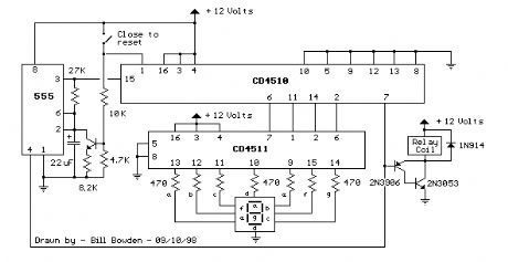
This circuit provides a visual 9 second delay using a 7 segment digital readout LED. When the switch is closed, the CD4010 up/down counter is preset to 9 and the 555 timer is disabled with the output held high. When the switch is opened, the timer produces an approximate 1 second clock signal, decrementing the counter until the 0 count is reached. When the zero count is reached, the 'carry out' signal at pin 7 of the counter moves low, energizing the 12 volt relay and stopping the clock with a low signal on the reset line (pin 4). The relay will remain energized until the switch is again closed, resetting the counter to 9. The 1 second clock signal from the 555 timer can be adjusted slightly longer or shorter by increasing or decreasing the resistor value at pin 3 of the timer.
The CD4510 is a CMOS Presettable BCD Up/Down counter which can be preset to any number between 0 and 9 with a high level on the PRESET ENABLE line, (pin 1) or reset to 0 with a high level on the RESET line (pin 9). Inputs for presetting the counter (P1, P2, P3, P4) are on pins (4, 12, 13, 3) respectively. The counter advances up or down on each positive-going clock transition (pin 15) and the counting direction (up or down) is controlled by the logic level on the UP/DOWN input (pin 10, high=up, low=down). The CARRY-IN signal (pin 5) disables the counter with a high logic level. (View)
View full Circuit Diagram | Comments | Reading(2795)
9 Second LED Timer and Relay Circuit
Published:2012/10/22 1:28:00 Author:muriel | Keyword: 9 Second , LED Timer, Relay Circuit
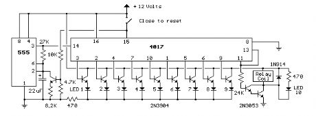
This circuit provides a visual 9 second delay using 10 LEDs before closing a 12 volt relay. When the reset switch is closed, the 4017 decade counter will be reset to the 0 count which illuminates the LED driven from pin 3. The 555 timer output at pin 3 will be high and the voltage at pins 6 and 2 of the timer will be a little less than the lower trigger point, or about 3 volts. When the switch is opened, the transistor in parallel with the timing capacitor (22uF) is shut off allowing the capacitor to begin charging and the 555 timer circuit to produce an approximate 1 second clock signal to the decade counter. The counter advances on each positive going change at pin 14 and is enabled with pin 13 terminated low. When the 9th count is reached, pin 11 and 13 will be high, stopping the counter and energizing the relay. Longer delay times can be obtained with a larger capacitor or larger resistor at pins 2 and 6 of the 555 timer. (View)
View full Circuit Diagram | Comments | Reading(1789)
Power-Off Time Delay Relay
Published:2012/10/22 1:28:00 Author:muriel | Keyword: Power-Off Time, Delay Relay
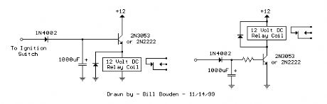
The two circuits below illustrate opening a relay contact a short time after the ignition or ligh switch is turned off. The capacitor is charged and the relay is closed when the voltage at the diode anode rises to +12 volts. The circuit on the left is a common collector or emitter follower and has the advantage of one less part since a resistor is not needed in series with the transistor base. However the voltage across the relay coil will be two diode drops less than the supply voltage, or about 11 volts for a 12.5 volt input. The common emitter configuration on the right offers the advantage of the full supply voltage across the load for most of the delay time, which makes the relay pull-in and drop-out voltages less of a concern but requires an extra resistor in series with transistor base. The common emitter (circuit on the right) is the better circuit since the series base resistor can be selected to obtain the desired delay time whereas the capacitor must be selected for the common collector (or an additional resistor used in parallel with the capacitor). The time delay for the common emitter will be approximately 3 time constants or 3*R*C. The capacitor/resistor values can be worked out from the relay coil current and transistor gain. For example a 120 ohm relay coil will draw 100 mA at 12 volts and assumming a transistor gain of 30, the base current will be 100/30 = 3 mA. The voltage across the resistor will be the supply voltage minus two diode drops or 12-1.4 = 10.6. The resistor value will be the voltage/current = 10.6/0.003 = 3533 or about 3.6K. The capacitor value for a 15 second delay will be 15/3R = 1327 uF. We can use a standard 1000 uF capacitor and increase the resistor proportionally to get 15 seconds. (View)
View full Circuit Diagram | Comments | Reading(1460)
Power-On Time Delay Relay
Published:2012/10/22 1:27:00 Author:muriel | Keyword: Power-On Time, Delay Relay
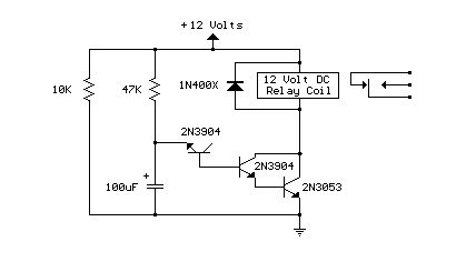
Here's a power-on time delay relay circuit that takes advantage of the emitter/base breakdown voltage of an ordinary bi-polar transistor. The reverse connected emitter/base junction of a 2N3904 transistor is used as an 8 volt zener diode which creates a higher turn-on voltage for the Darlington connected transistor pair. Most any bi-polar transistor may be used, but the zener voltage will vary from about 6 to 9 volts depending on the particular transistor used. Time delay is roughly 7 seconds using a 47K resistor and 100uF capacitor and can be reduced by reducing the R or C values. Longer delays can be obtained with a larger capacitor, the timing resistor probably shouldn't be increased past 47K. The circuit should work with most any 12 volt DC relay that has a coil resistance of 75 ohms or more. The 10K resistor connected across the supply provides a discharge path for the capacitor when power is turned off and is not needed if the power supply already has a bleeder resistor. (View)
View full Circuit Diagram | Comments | Reading(3506)
Low Voltage, High Current Time Delay Circuit
Published:2012/10/22 1:26:00 Author:muriel | Keyword: Low Voltage, High Current , Time Delay Circuit
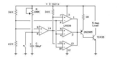
In this circuit a LM339 quad voltage comparator is used to generate a time delay and control a high current output at low voltage. Approximatey 5 amps of current can be obtained using a couple fresh alkaline D batteries. Three of the comparators are wired in parallel to drive a medium power PNP transistor (2N2905 or similar) which in turn drives a high current NPN transistor (TIP35 or similar). The 4th comparator is used to generate a time delay after the normally closed switch is opened. Two resistors (36K and 62K) are used as a voltage divider which applies about two-thirds of the battery voltage to the (+) comparator input, or about 2 volts. The delay time after the switch is opened will be around one time constant using a 50uF capacitor and 100K variable resistor, or about (50u * 100K) = 5 seconds. The time can be reduced by adjusting the resistor to a lower value or using a smaller capacitor. Longer times can be obtained with a larger resistor or capacitor. To operate the circuit on higher voltages, the 10 ohm resistor should be increased proportionally, (4.5 volts = 15 ohms). (View)
View full Circuit Diagram | Comments | Reading(965)
Capacitor Discharge Ignition Circuit (CDI)
Published:2012/10/22 1:26:00 Author:muriel | Keyword: Capacitor Discharge, Ignition Circuit (CDI)
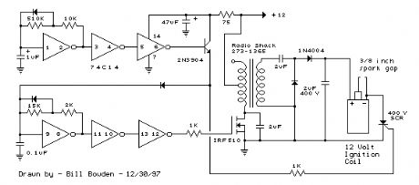
The CDI ignition circuit produces a spark from an ignition coil by discharging a capacitor across the primary of the coil. A 2uF capacitor is charged to about 340 volts and the discharge is controlled by an SCR. A Schmitt trigger oscillator (74C14) and MOSFET (IRF510) are used to drive the low voltage side of a small (120/12 volt) power transformer and a voltage doubler arrangement is used on the high voltage side to increase the capacitor voltage to about 340 volts. A similar Schmitt trigger oscillator is used to trigger the SCR about 4 times per second. The power supply is gated off during the discharge time so that the SCR will stop conducting and return to it's blocking state. The diode connected from the 3904 to pin 9 of the 74C14 causes the power supply oscillator to stop during discharge time. The circuit draws only about 200 milliamps from a 12 volt source and delivers almost twice the normal energy of a conventional ignition circuit. High voltage from the coil is about 10KV using a 3/8 inch spark gap at normal air temperature and pressure. Spark rate can be increased to possibly 10 Hertz without losing much spark intensity, but is limited by the low frequency power transformer and duty cycle of the oscillator. For faster spark rates, a higher frequency and lower impedance supply would be required. Note that the ignition coil is not grounded and presents a shock hazard on all of it's terminals. Use CAUTION when operating the circuit. An alternate method of connecting the coil is to ground the (-) terminal and relocate the capacitor between the cathode of the rectifier diode and the positive coil terminal. The SCR is then placed between ground and the +340 volt side of the capacitor. This reduces the shock hazard and is the usual configuration in automotive applications. (View)
View full Circuit Diagram | Comments | Reading(1912)
Voltage Regulator (13.6 volts)
Published:2012/10/22 1:23:00 Author:muriel | Keyword: Voltage Regulator, 13.6 volts
View full Circuit Diagram | Comments | Reading(755)
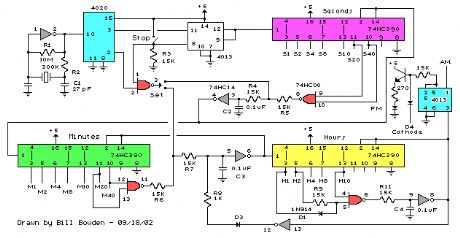
Clock Timer Circuit
Published:2012/10/22 1:22:00 Author:muriel | Keyword: Clock Timer
View full Circuit Diagram | Comments | Reading(901)
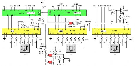
Clock Display Circuit
Published:2012/10/22 1:21:00 Author:muriel | Keyword: Clock Display Circuit
View full Circuit Diagram | Comments | Reading(1893)
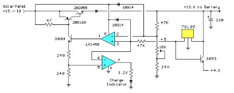
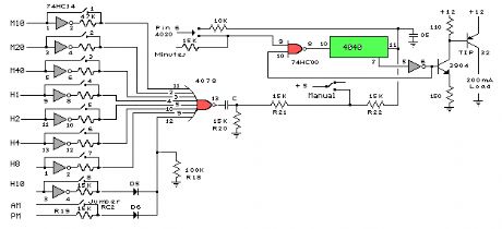
Digital Clock with Timer and Solar Panel Regulator
Published:2012/10/22 1:21:00 Author:muriel | Keyword: Digital Clock, Timer, Solar Panel Regulator
This is a combination digital clock timer and solar panel charge controller used to maintain a deep cycle battery from a solar panel. The timer output is used to control a 12 volt load for a 32 minute time interval each day. Start time is set using 9 dip switches and ends 32 minutes later. The 32 minute duration is set by selecting the 5th bit (2^5 = 32) of a 4040 binary counter (pin 2). The timer also has a manual toggle switch so the load can be manually switched on or off and automatically shuts off after 32 minutes. The time duration can be longer or shorter (8,16,32,64,128,256 minutes etc.) by selecting the appropriate bit of the counter. The timer circuit is shown in the lower schematic just above the regulator.
The basic clock circuit (top schematic below) is similar to the binary clock (on another page) and uses 7 ICs to produce the 20 digital bits for 12 hour time, plus AM and PM. A standard watch crystal oscillator (32,768) is used as the time base and is divided down to 1/2 half second by the 4020 binary counter. One half of a 4013 data latch is used to divide the 1/2 second signal by 2 and produce a one second pulse that drives the seconds counter (74HC390 colored purple). The minutes are advanced by decoding 60 seconds (40 + 20) and then resetting the seconds counter to 0 and at the same time advancing the minutes counter. The same procedure is used to advance the hours. The second half of the 4013 latch is used to indicate AM or PM and is toggled by decoding 13 hours and resetting the hours to 0 and then advancing the hours to one . (View)
View full Circuit Diagram | Comments | Reading(2197)
Binary Coded Decimal (BCD) Clock
Published:2012/10/22 1:20:00 Author:muriel | Keyword: Binary Coded Decimal (BCD), Clock
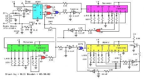
The clock circuit above uses seven ICs and 19 LEDs to indicate binary coded decimal time. The LEDs can be arranged (as shown in example above) so that each horizontal group of 3 or 4 LEDs represents a decimal digit between 0 and 9 and each individual LED represents a single bit or (binary digit) of the value. Binary digits have only two values (0 and 1) so a number written in binary would be something like 1001 or 0011, which represents decimal numbers 9 and 3 respectively. From right to left, each binary (1) represents increasing powers of 2, so that a 1 in the right hand place represents 2^0=1 and the next place to the left is 2^1=2 and then 2^2=4, and so forth. This makes binary counting fairly easy since each digit has a value of twice the one before or 1,2,4,8,16,32,64,etc. Thus the decimal value can be found by simply adding the values of each illuminated LED in the same row, (the total is shown in the box to the right). For example, the binary number 1001 would have a decimal value of 8+0+0+1 = 9. But this is actually a binary coded decimal 9 since only values from 0 to 9 are used 0000 to 1001. A true binary clock indicating minutes of the hour would display values from 0 to 59, or 000000 to 111011. But this would be more difficult to read since adding values 32 + 16 + 8 + 2 + 1 = 59 is not as easy as 8 + 0 + 0 + 1 = 9.
The circuit is powered by a small 12.6 VAC transformer which also provides a low voltage 60 Hz signal for a very accurate time base. The transformer is connected with the secondary center tap at ground which produces about 8 volts DC across the 3300uF filter capacitor. DC power for the circuit is regulated at about 5.5 using a NPN transistor (2N3053) and 6.2 volt zener diode. The 2N3053 gets a little warm when several LEDs are on, and may require a little (top hat type) heat sink. (View)
View full Circuit Diagram | Comments | Reading(1822)
PIC Digital Clock Timer
Published:2012/10/22 1:18:00 Author:muriel | Keyword: PIC , Digital Clock, Timer
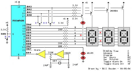
This clock timer uses a PIC16F628 microcontroller to display 3 and 1/2 digit time and control an external load. The clock includes a calendar with leap year and optional daylight savings adjustments. The timer output can be set from 1 to 59 minutes and manually switched on and off. The clock also has a correction feature that allows an additional second to be added every so many hours to compensate for a slightly slow running oscillator. The oscillator uses a common 32.768 KHz watch crystal and the frequency can be adjusted slightly with the 24pF capacitor on the right side of the crystal. (View)
View full Circuit Diagram | Comments | Reading(3235)
40 LED Bicycle Light
Published:2012/10/22 1:16:00 Author:muriel | Keyword: 40 LED, Bicycle Light
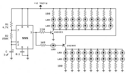
The 555 circuit below is a flashing bicycle light powered with four C,D or AA cells (6 volts). Two sets of 20 LEDs will alternately flash at approximately 4.7 cycles per second using RC values shown (4.7K for R1, 150K for R2 and a 1uF capacitor). Time intervals for the two lamps are about 107 milliseconds (T1, upper LEDs) and 104 milliseconds (T2 lower LEDs). Two transistors are used to provide additional current beyond the 200 mA limit of the 555 timer. A single LED is placed in series with the base of the PNP transistor so that the lower 20 LEDs turn off when the 555 output goes high during the T1 time interval. The high output level of the 555 timer is 1.7 volts less than the supply voltage. Adding the LED increases the forward voltage required for the PNP transistor to about 2.7 volts so that the 1.7 volt difference from supply to the output is insufficient to turn on the transistor. Each LED is supplied with about 20 mA of current for a total of 220 mA. The circuit should work with additional LEDs up to about 40 for each group, or 81 total. The circuit will also work with fewer LEDs so it could be assembled and tested with just 5 LEDs (two groups of two plus one) before adding the others. (View)
View full Circuit Diagram | Comments | Reading(2209)
25 Light Sequencer using Xmas lamps
Published:2012/10/22 1:15:00 Author:muriel | Keyword: 25 Light Sequencer, Xmas lamps
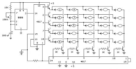
This circuit is same as the above setup to drive 25 small Xmas lights. The lights operate at about 200mA and 3 volts. The supply voltage is set to 5 volts and the 4017 counter output will drop about a volt using the 2N3053 transistors. The voltage on the emitters of the rows transistors will be about 0.7 volts less than the base so the lamp voltage will be about 3 volts. You can adjust the supply voltage for the desired current if necessary. It works the same way as the LED version but you need diodes in series with each light. Most any small diode rated at 500mA or more should work. I used 1N4001 diodes. Various NPN transistors can be used, I tried 2N2219A and 2N3053. The 2N3053 worked out better with a higher gain than the 2N2219A, but either one should work. (View)
View full Circuit Diagram | Comments | Reading(2550)
| Pages:297/2234 At 20281282283284285286287288289290291292293294295296297298299300Under 20 |
Circuit Categories
power supply circuit
Amplifier Circuit
Basic Circuit
LED and Light Circuit
Sensor Circuit
Signal Processing
Electrical Equipment Circuit
Control Circuit
Remote Control Circuit
A/D-D/A Converter Circuit
Audio Circuit
Measuring and Test Circuit
Communication Circuit
Computer-Related Circuit
555 Circuit
Automotive Circuit
Repairing Circuit