
Circuit Diagram
Index 1267
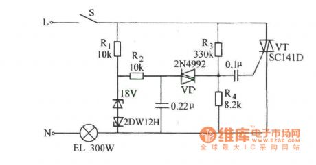
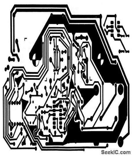
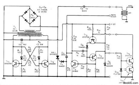
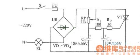
The filament lamp dual-channel thyristor lifespan prolonging circuit
Published:2011/7/21 3:17:00 Author:Seven | Keyword: filament lamp, dual-channel thyristor
View full Circuit Diagram | Comments | Reading(745)
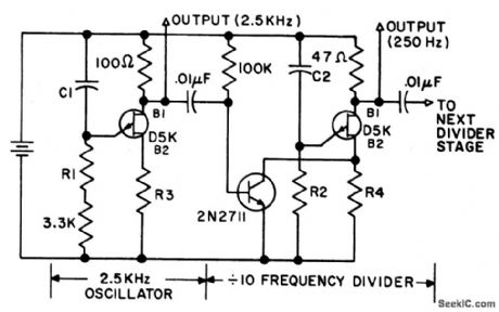
DECADE_FREQUENCY_DIVIDER
Published:2009/6/28 23:05:00 Author:May
View full Circuit Diagram | Comments | Reading(862)
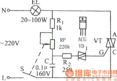
The thyristor stageless light and speed regulator circuit
Published:2011/7/21 3:18:00 Author:Seven | Keyword: thyristor, stageless, speed regulator
View full Circuit Diagram | Comments | Reading(519)
DIGITAL_TACHOMETER
Published:2009/6/28 23:05:00 Author:May
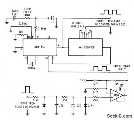
Pulses from auto engine points or other pickoff are filtered before feed to 3130 CMOS opamp used as comparator to complete conditioning of input. Pulses are then fed through 4046 PLL to divide-by-N counter that is set for number of cylinders in engine (60 for four cylinders, 45 for six, and 30 for eight). Output frequency is then counted for 0.5 s to get engine or shah speed in rpm.-D. Lancaster, CMOS Cookbook, Howard W. Sams, Indianapolis, IN, 1977, p 36-367. (View)
View full Circuit Diagram | Comments | Reading(2821)
_5_V_from_a_charge_pump_low_power
Published:2009/7/25 4:16:00 Author:Jessie
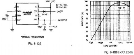
Figure 8-122 shows a MAX660 charge pump connected to provide -5 V at low power. Figure 8-123 shows the efficiency curve. The input voltage range is 1.5 V to 5.5 V, output impedance is 6.5 (1, quiescent current is 100 μA (VIN = 5 V). maximum load current is 100 mA (VIN = 4.75 V), and shutdown current is 10 μA. The circuit is low noise, with a fixed-frequency oscillation (between 10 and 45 kHz), and with an unregulated output (output voltage follows input variations). MAXIM BATTERY MANAGEMENT CIRCUIT COLLECTION, 1994, P. 60.
(View)
View full Circuit Diagram | Comments | Reading(640)
SWR_METER
Published:2009/6/28 23:03:00 Author:May
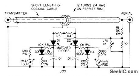
Gives direct measurement of standingwave ratio on transmission line, independent of absolute power levels and of frequency. Voltages of 1N4002 silicon diodes are proportional to logarithms of their cuffents, which in tum are proportional to forward and reflected voltages. Meter scale is nonlinear, with maximum sensitivity as SWR approaches 1:1. For 50-ohm Iine, use 220 for R2 and 27 for R3 and R4. For 75-ohm line, corresponding values are 180 and 33. Detector diodes are pointcontact germanium rated at 80 PIV. Articlegives construction details and calibration curve. Ferrite ring is Mullard FX1596 or equivalent, with 0.5-inch outside diameter. Ground coax braid at one end only.-P. G. Martin, Some Directional Wattmeters and a Novel SWR Meter, 73 Mag-azine, Aug. 1974, p 17, 19-21, 23-24, and 26. (View)
View full Circuit Diagram | Comments | Reading(8494)
IC_precision_oscillator
Published:2009/7/25 4:15:00 Author:Jessie
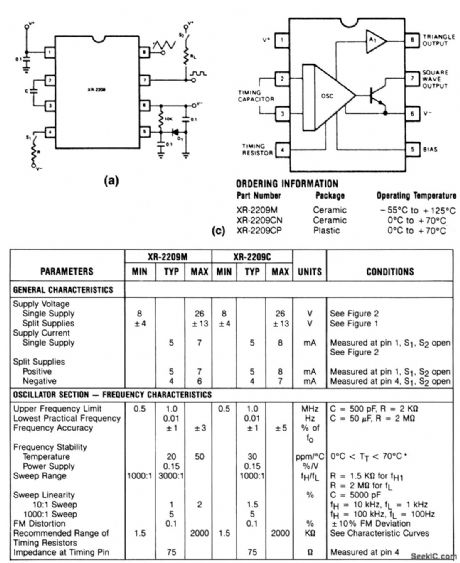


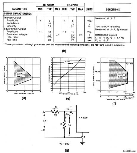

This circuit uses an XR-2209 to provide simultaneous triangle and square outputs over a frequency range of 0.01 Hz to 1 MHz, with a typical drift of 20 ppm/℃. The output can be swept over a 1000:1 range with an external control voltage. Electrical characteristics and functional circuits of the XR-2209 are shown in Figs. 5-44B and 5-44C, respectively. Operating frequency is set by capacitor C between pins 2 and 3, and the timing resistor at pin 4. Use a 1N4148 or equivalent for D1. See Conditions in Fig. 5-44B. Figure 5-44G shows connections for frequency-sweep operation. The frequency of such operation is determined by: (View)
View full Circuit Diagram | Comments | Reading(912)
BROADBAND_NOISE_AMPLIFIER
Published:2009/6/28 23:02:00 Author:May
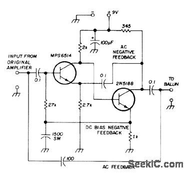
Developed for use with antenna noise bridges for measurements at 20 meters. Provides 35 to 50 dB additional gain, not entirely constant over use-ful range of 1.8 to 30 MHz. Three strong feedback loops are introduced between drivor and final amplifier Use transistors specified, because substitutions may cut overall gain by 10 to 20 dB.-A Weiss、Noise Bridge,Ham Radio,May 1974、p 71-72 (View)
View full Circuit Diagram | Comments | Reading(863)
Wide_range_function_generator
Published:2009/7/25 3:44:00 Author:Jessie
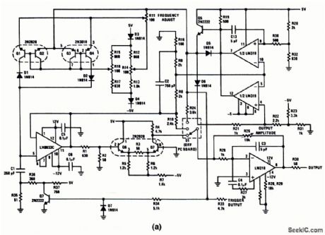
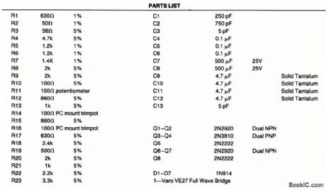
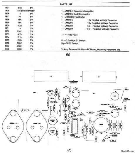
This circuit produces all three waveforms(sine, triangle, square)as selected by S1、at frequencies from 10 Hz to 1 MHz,Output amplitude is set by R25 Output frequency is set by R11.Figures 5-24B, 5-24C, 5-24D、and show parts list, recommended component location, PC layout and Power supply, respectively. To calibrate, set R11 for 1-MHz output and adjust R16 for proper output symmetry.Then,set R11 for 10 Hz and adjust R14 for good symmetry. (View)
View full Circuit Diagram | Comments | Reading(0)
OPTOELECTRONIC_IGNlTION
Published:2009/6/28 23:02:00 Author:May
Combination of Iow-cost point-source LED and high-sensitivity phototransistor forms optical sensor for posi-tion of cam in distributor, Technique eliminates problems created by timing drift and distribu-tor-shaft play. Sensor head is small enough to fit most distributors. Article gives dimensioned drawings for shutter design and sensor mount-ing, and describes operation of associated capacitor-discharge electronic ignition circuit in detail. Leads to sensor do not require shielding.-H. Maidment, Optical Sensor lgnition System, Wireless World, Nov.1975, p 533-537. (View)
View full Circuit Diagram | Comments | Reading(1520)
CMOS_staircase_generator
Published:2009/7/25 3:40:00 Author:Jessie
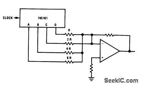
This circuit uses a 74C161 and any suitable op amp (such as an LM301) to form a staircase generator. Linearity of the staircase depends on precision of the resistors. (View)
View full Circuit Diagram | Comments | Reading(1224)
OIL_LEVEL_GAGE
Published:2009/6/28 22:55:00 Author:May

Permits checking crankcase oil Ievel from driver's seat. Sensor consists of light-conducting Plexiglas rod attached to dipstick, with lamp L1 at top of rod and phototransistor Q1 mounted at add-oil mark on dipstick, about 1/2 inch below bottom of rod. At normal oil level, oil attenuates light between a, and bottom end of rod, making phototransistor resistance high. Pushing test switch makes C1 charge and saturate Q2 long enough to activate UJT AF oscillator Q3 and give short tone verifying that lamp is not bumed out and gage is working. When oil is Iow, enough Iight reaches Q1 to keep O2 saturated after C1 charges, giving continuous tone as long as switch is pushed.-L. Svelund, Electronic Dipstick, EEE Magazine, Nov. 1970, p 101. (View)
View full Circuit Diagram | Comments | Reading(719)
74 Series digital circuit of 74279,74LS279 four R-S latch
Published:2011/8/1 1:50:00 Author:Lucas | Keyword: 74 Series , digital circuit , four R-S latch
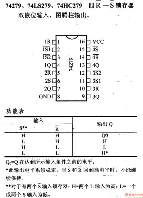
74279,74LS279, 74HC279four R-S latch
Double-clamped input, totem pole output
Q0 =the output level before establishing the steady-state input conditions.
If the output level is stable, when the S and R simultaneously reach high level, the state can not be maintained. For the latch with two S inputs; H = two L inputs, which is high; L = one or two S inputs ,which is low.
(View)
View full Circuit Diagram | Comments | Reading(3401)
CMOS_one_shot
Published:2009/7/25 3:39:00 Author:Jessie
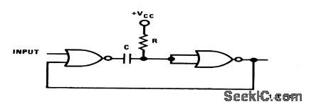
This circuit uses two sections ofan MM74C02 to form a one-shot. (View)
View full Circuit Diagram | Comments | Reading(852)
AUDIBLE_TURN_SIGNAL
Published:2009/6/28 22:52:00 Author:May
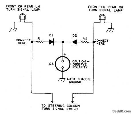
Gives 3500-Hz audible tone each time turn-signal light flashes on, to warn driver that signal has not been turned off when making less than right-angle turns.Schematic shown is for 12-V negative-ground systems. For 6.V negative-ground systems, cut values of R1 and R2 about in half. For positiveground systems, reverse connections to diodes and Sonalert.R1 and R2 are 2.7K 0.5 VV. D1 and D2 can be any general-purpose small-current silicon diode. SA is Mallory SC1.5 Sonalert.-A. Goodwin, Turn Signal Reminder, 73 Magazine, Holiday issue 1976, p 166. (View)
View full Circuit Diagram | Comments | Reading(628)
CMOS_square_wave_generator
Published:2009/7/25 3:38:00 Author:Jessie
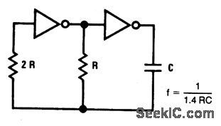
This circuit uses two sections of an MM74C04 to form a square-wave oscillator. (View)
View full Circuit Diagram | Comments | Reading(747)
The thyristor light regulation circuit
Published:2011/7/21 3:19:00 Author:Seven | Keyword: thyristor, light regulation
View full Circuit Diagram | Comments | Reading(1037)
CMOS_phase_shift_oscillator
Published:2009/7/25 3:37:00 Author:Jessie
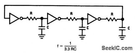
This circuit uses three sections of an MM74C04 to form a phase shift oscillator. (View)
View full Circuit Diagram | Comments | Reading(654)
The dual-thyristor controlled 3-phase heating part circuit
Published:2011/7/21 3:20:00 Author:Seven | Keyword: dual-thyristor, 3-phase
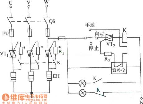
View full Circuit Diagram | Comments | Reading(809)
PIN_DIGDE_ATTENUATOR
Published:2009/6/28 22:51:00 Author:May
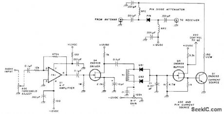
Designed for insertion between antenna and input of any HF receiver to improve adjacent-channel selectivity by providing attenuation ahead of mixer for entire tuning range. Hewlett-Packard 5082-3379 PIN diode has very low impedance when conducting and very high impedance when biascurrent is small. NPN transistor Q1 provides over 100 mA as current source to PIN diode. Q1 is driven by AGO circuit through JFET buffer Q3.AGC voltage is derived from top of audio gain control in receiver for rectification, with 200 mVRMS at input of opamp U1 giving maximum attenuation. Center tap of T1 (any small AF transformer) can be grounded. CR1 and CR2 are germanium diodes. Article also gives circuit of IF system using cascaded 9-MHz crystal filters to improve selectivity further and provide over all AGC control range of 70 dB.-M. Goldstein, Improved Receiver Selectivity and Gain Control, Ham Radio, Nov. 1977, p 71-73. (View)
View full Circuit Diagram | Comments | Reading(1872)
| Pages:1267/2234 At 2012611262126312641265126612671268126912701271127212731274127512761277127812791280Under 20 |
Circuit Categories
power supply circuit
Amplifier Circuit
Basic Circuit
LED and Light Circuit
Sensor Circuit
Signal Processing
Electrical Equipment Circuit
Control Circuit
Remote Control Circuit
A/D-D/A Converter Circuit
Audio Circuit
Measuring and Test Circuit
Communication Circuit
Computer-Related Circuit
555 Circuit
Automotive Circuit
Repairing Circuit