
Circuit Diagram
Index 1261
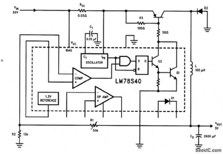
Step_up_converter_with_adjustable_output
Published:2009/7/25 1:38:00 Author:Jessie
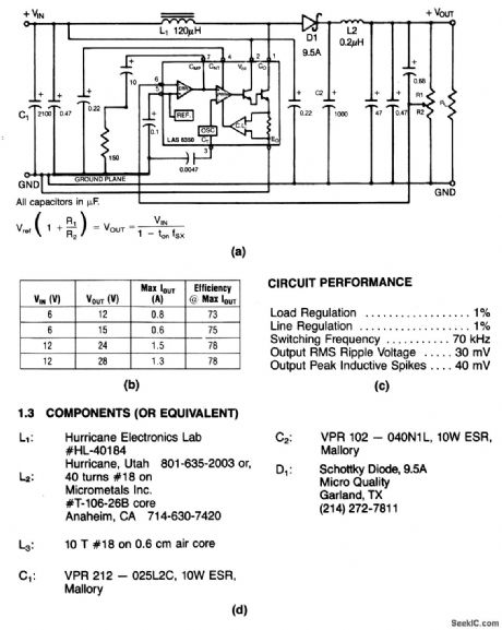
This circuit provides an adjustable output at 1.5 A. Typical performance, circuit performance, and component sources are shown in Figs. 4-29B, 4-29C, and 4-29D, respectively. (View)
View full Circuit Diagram | Comments | Reading(607)
Triple_output_supply_5V_at_5A_±12V_at_125mA
Published:2009/7/25 1:36:00 Author:Jessie
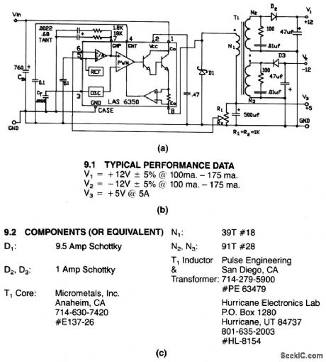
This circuit provides an adjustable +5-V and fixed ±12-V outputs,Figure 4-28B shows typical performance data,Figure 4-28C shows component source information. (View)
View full Circuit Diagram | Comments | Reading(759)
Norton_lamp_relay_driver_300_mA_loads
Published:2009/7/25 1:36:00 Author:Jessie
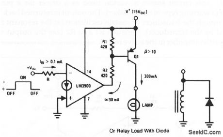
This circuit is similar to that of Fig. 11-10, except that the load capability is increased to 300 mA. R1 and R2 hold Q2 off when the Norton OTA output is high. R2 limits the base drive when Q1 goes on. Pin 14 must tie to the same power supply as the emitter of Q1 to guarantee that Q1 can be held off. For inductive loads, such as a relay coil, a backswing diode must be added to prevent large inductive voltage kicks during the on/off switching interval. (View)
View full Circuit Diagram | Comments | Reading(731)
Dual_output_supply_±5_V
Published:2009/7/25 1:35:00 Author:Jessie
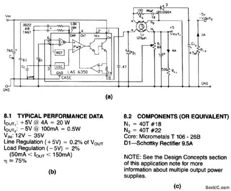
This circuit provides an adjustable +5-V and a fixed -5-V output. Figure 4-27B shows typical performance data.Figure 4-27C shows component source information. (View)
View full Circuit Diagram | Comments | Reading(693)
Norton_lamp_relay_driver_20__to_30_mA_loads
Published:2009/7/25 1:34:00 Author:Jessie

This circuit uses a Norton to drive low-power lamps and relays (such as reed relays). Note that the value of R must be selected such that VIN supplies at least 0.1 mA of input current. (View)
View full Circuit Diagram | Comments | Reading(691)
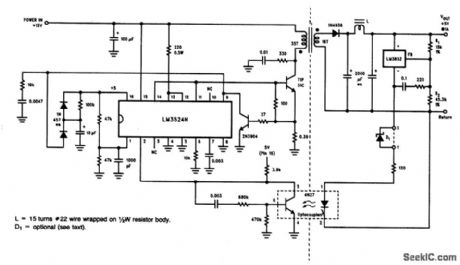
2_A_converter_with_extended_remote_sensing
Published:2009/7/25 1:33:00 Author:Jessie
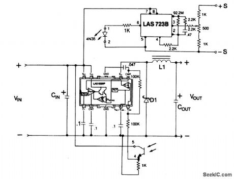
This circuit provides an adjustable output voltage through operation of a remote regulator and a 4N35 optocoupler. (View)
View full Circuit Diagram | Comments | Reading(1166)
Low Frequency Multi Wave Form Generator Circuit
Published:2011/7/22 21:13:00 Author:Joyce | Keyword: Low Frequency, Multi Wave Form, Generator
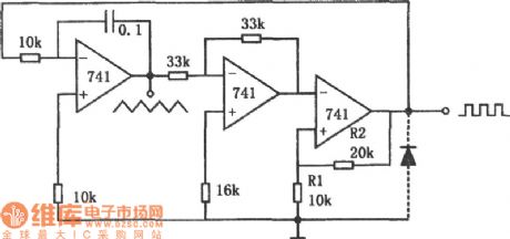
As shown in the figure is a low frequency multi waveform generator circuit. This circuit can output two kinds of waveform simultaneously: triangle wave and square wave. In the circuit, the first stage is a standard integrator; the second stage is a phase inverter whose gain is 1; the third stage is a hysteretic comparator. When the third stage does not have a diode, output of the circuit is positive, output of the integrator is negative inclined wave, which will turn into positive inclined wave after being inverted and will then be added to the comparator. (View)
View full Circuit Diagram | Comments | Reading(2316)
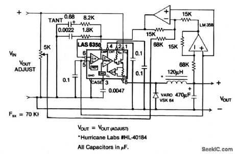
5_A_converter_with_high_input_voltage
Published:2009/7/25 1:32:00 Author:Jessie
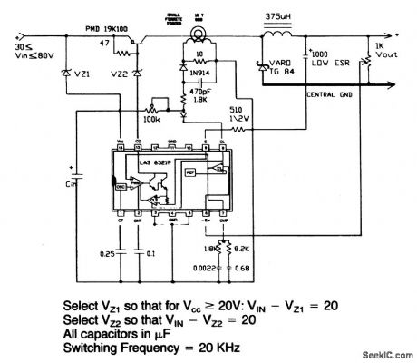
This circuit provides an adjustable output voltage,and it can beoperated with input voltages between 30 and 80 V. (View)
View full Circuit Diagram | Comments | Reading(656)
30__to_5_V_at_20_A_converter
Published:2009/7/25 1:31:00 Author:Jessie
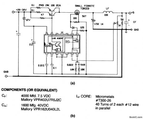
This circuit provides an adjustable output voltage. Figure 4-24B shows component source information. (View)
View full Circuit Diagram | Comments | Reading(553)
555 Brightness display circuit
Published:2011/7/21 3:09:00 Author:Ecco | Keyword: 555 , Brightness, display

As shown in Figure 7-32, brightness display circuit includes light sensor, the oscillation circuit and diode display circuit. Photoresistor RG is used as a shunt resistor in 555 oscillator charging loop, with the changing of background light intensity, it shows different resistance, thus affecting the oscillation frequency and the duty cycle of oscillation waveform. When the light intensity increases, the oscillation frequency increases, and the duty cycle reduces, the brightness of light-emitting diode LED increases.
(View)
View full Circuit Diagram | Comments | Reading(1397)
38__to_14_V_at_40_A_converter
Published:2009/7/25 1:30:00 Author:Jessie
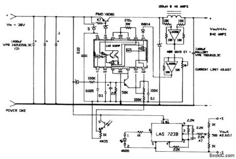
This circuit provides both an adjustable output voltage and an adjustable currentlimit. (View)
View full Circuit Diagram | Comments | Reading(595)
Step_down_converter_with_zero_outyout_capability
Published:2009/7/25 1:28:00 Author:Jessie
This circuit can be adjusted from 5 down to 0 V. (View)
View full Circuit Diagram | Comments | Reading(692)
Isolated_regulator
Published:2009/7/25 3:09:00 Author:Jessie


This optocoupler-based circuit provides galvanically isolated, regulated voltage. The output is +5 V at 1 A with the values shown. The output can be fixed at any value between 3.2 and 25 V, by selecting R2, using R2= R1 (VOUT -1.25)/1.25. If VOUT is greater than 6 V, insert Zener D1 between point X and Y, with Vz= Vour - 5 V. This prevents the voltage across the LM385 from exceeding the 5.4-V max, limit (View)
View full Circuit Diagram | Comments | Reading(1968)
Inverting_regulator
Published:2009/7/25 3:05:00 Author:Jessie
This circuit converts 12-V to an adjustable -15-V output at 500 mA,with less than 1%ripple. (View)
View full Circuit Diagram | Comments | Reading(1043)
Wien Oscillation Audio Signal Generator Circuit
Published:2011/7/21 21:35:00 Author:Joyce | Keyword: Wien , Oscillation, Audio , Signal, Generator
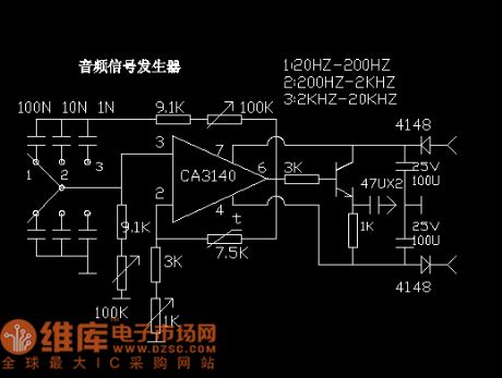
Output frequency: 20 HZ -20 KHZ. Output amplitude: 2 V.It is simple, but has excellent performance and will meet the requirement of DIY acoustic equipment. Principle of the circuit: Operational amplifier CA3140 works as the major amplifier, 100 K potentiometer and phase shifting capacitance compose phase shift, positive feedback and frequency-selective network. 1 K potentiometer and thermistor constitute a negative feedback amplitude-stabilized circuit. Audio signal is output via the follower. (View)
View full Circuit Diagram | Comments | Reading(750)
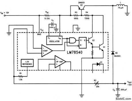
Step_down_voltage_regulator_with_increased_current_ratings
Published:2009/7/25 3:04:00 Author:Jessie
This circuit is similar to that of Fig.4-67,except that the input is 30 V,and the output is 5V at 5A. (View)
View full Circuit Diagram | Comments | Reading(693)
Norton_ultra_linear_tuzo_decade_VCO
Published:2009/7/25 2:13:00 Author:Jessie
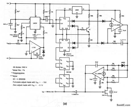
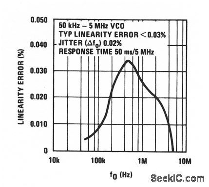
In this circuit, a Norton is used to drive a fast PLL to form a VCO (which is essentially a form of V/F converter described in chapter 12). The frequency range is from 50 kHz to 5 MHz. Figure 11-23B shows the linearity error over the frequency range. To calibrate, monitor the output with a frequency counter, apply the voltages shown at VIN, and adjust both the zero and full-scale pots for the correct frequency. (View)
View full Circuit Diagram | Comments | Reading(797)
Multi_output_converter_with_low_quiescent_current
Published:2009/7/25 2:10:00 Author:Jessie
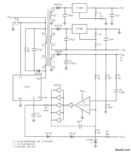
This circuit provides 5-V output at 1 A, and ±12-V outputs from 12-V input, with about 100-mA quiescent current. (View)
View full Circuit Diagram | Comments | Reading(702)
PREAMP_WITH_TEST_TONE
Published:2009/6/28 23:35:00 Author:May
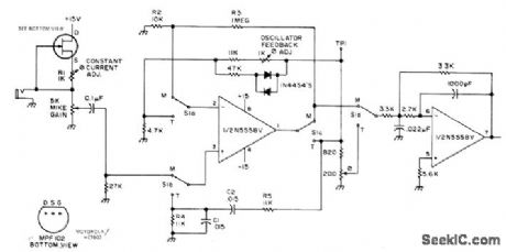
Built around Signetics N5558V dual opamp or equivalent Motorola MC1458CP2, National LM1458, or Texas Instruments SN72558P. First half of opamp is used either as gain stage for increasing voltage level of carbon microphone or as AF Wienbridge tone oscillator, depending on position of S1. Frequency is determined byvaluesof C1, C2, R4 and R5. Silicon signal diodes form nonlinear control element. Adjust R6 until oscillator out-put at TPt is 10 V P-P. FET provides constant current through variable resistance of carbon microphone, to give audio input voltage. Sec-ond opamp is active low-pass filter with 3.3-kHz cutoff, rolloff of 12 dB per octave, and voltage gain of 10.-H. Olson, An IC Mike Preamp That Doubles as a Tone Generator, 73 Magazine, March 1974, p 45 and 47-48. (View)
View full Circuit Diagram | Comments | Reading(1538)
Norton_high_corrtmon_mode_voltage_difference_amplifier
Published:2009/7/25 2:06:00 Author:Jessie
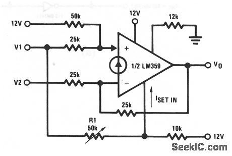
In this circuit, the Norton amplifies the difference in voltage between V1 and V2, but both inputs can be riding on a common-mode (chapter 10) level as high as about 250 Vdc without exceeding the maximum input current. By making the bias current (ISET) directly proportional to the input level, a 20-dB CMRR improvement is possible (when R1 is adjusted for maximum CMRR at the maximum input common-mode voltage). (View)
View full Circuit Diagram | Comments | Reading(746)
| Pages:1261/2234 At 2012611262126312641265126612671268126912701271127212731274127512761277127812791280Under 20 |
Circuit Categories
power supply circuit
Amplifier Circuit
Basic Circuit
LED and Light Circuit
Sensor Circuit
Signal Processing
Electrical Equipment Circuit
Control Circuit
Remote Control Circuit
A/D-D/A Converter Circuit
Audio Circuit
Measuring and Test Circuit
Communication Circuit
Computer-Related Circuit
555 Circuit
Automotive Circuit
Repairing Circuit