
Circuit Diagram
Index 1281
SINGLE_TRANSISTOR_PHASE_SHIFTER
Published:2009/6/28 20:40:00 Author:May
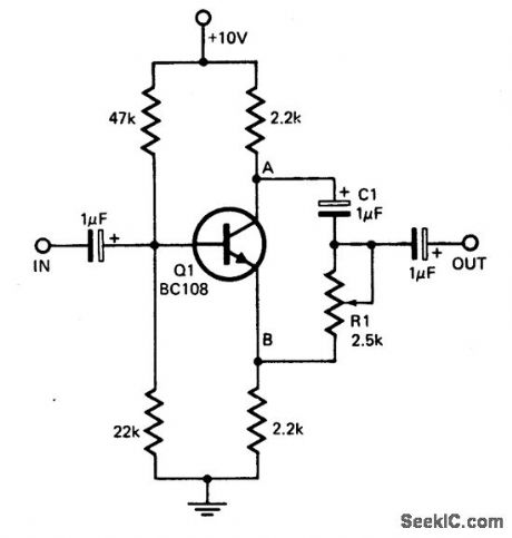
This circuit provides a simple means of obtaining phase shifts between zero and 170°.The transistor operates as a phase splitter, the output at point A being 180° out of phase with the input. Point B is in phase with the input phase. Adjusting R1 provides the sum of various proportions of these and hence a continuously variable phase shift is provided. The circuit operates well in the 600 Hz to 4 kHz range. (View)
View full Circuit Diagram | Comments | Reading(1862)
PHASE_SEQUENCE_INDICATOR
Published:2009/6/28 20:39:00 Author:May
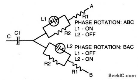
Simple, portable phase-sequence indicator determines the proper phase rotation in polyphase circuits. Major components are two neon lamps, two resistors, and a capacitor. In operation, the leg voltages are unbalanced, so that the lamp with the maximum voltage—or proper phase sequence—lights. Table shows typical component values for various circuit frequencies. (View)
View full Circuit Diagram | Comments | Reading(4879)
ac_VOLTAGE_PROBE
Published:2009/6/26 5:32:00 Author:May
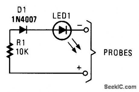
This simple probe can save your life by waming you of live circuitry. It's ideal for times when more than one person is working on a device. (View)
View full Circuit Diagram | Comments | Reading(1297)
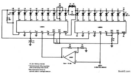
EXTENDED_RANGE_VU_METER(DOT_MODE)
Published:2009/6/28 21:05:00 Author:Jessie
View full Circuit Diagram | Comments | Reading(2606)
SIMPLE_VOLTAGE_PROBE
Published:2009/6/26 5:31:00 Author:May
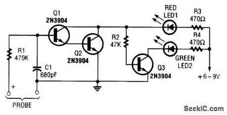
This simple voltage probe can be helpful in checking and troubleshooting solid-state circuitry. (View)
View full Circuit Diagram | Comments | Reading(1163)
PHOTOGRAPHIC_TIMER
Published:2009/6/28 21:04:00 Author:Jessie
View full Circuit Diagram | Comments | Reading(1257)
SHUTTER_TESTER
Published:2009/6/28 21:03:00 Author:Jessie
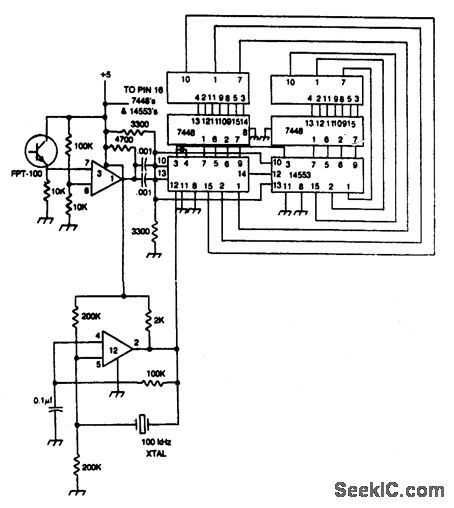
Shutter speed tester combines frequency counter, crystal oscillator, and photo-transistor-operated gate generator. Oscillator pulses are counted as long as the shutter is open. Reset is automatic at the instant the shutter opens.
(View)
View full Circuit Diagram | Comments | Reading(2303)
INEXPENSIVE_ISOLATION_TRANSFORMERIMPROMPTU_SETUP
Published:2009/6/26 5:17:00 Author:May
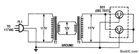
Using two 12-V filament or power transformers, an impromptu isolation transformer can be made for low-power(under 50 W) use in testing or servicing. SO1 is an ordinary, duplex ac receptable. Use heavy-wire connections between the 12-V windings because several amperes can flow. (View)
View full Circuit Diagram | Comments | Reading(0)
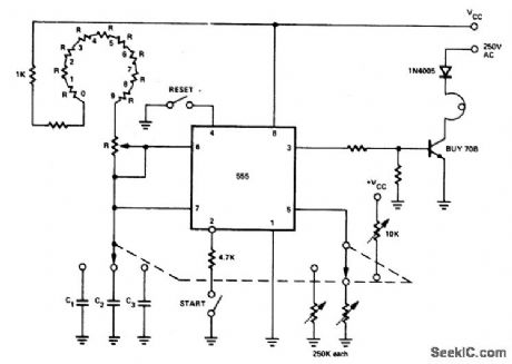
FLASH_EXPOSURE_METER
Published:2009/6/28 21:02:00 Author:Jessie
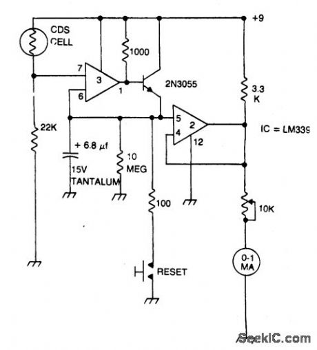
Strobe light meter catches the peak of flash intensity and holds it long enough to give a reading. The reset button must be pressed before each measurement. (View)
View full Circuit Diagram | Comments | Reading(1720)
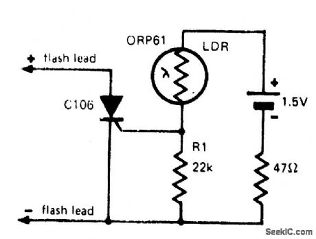
REMOTE_FLASH_TRIGGER
Published:2009/6/28 21:01:00 Author:Jessie

Transistor Q1 is a light-activated silicon-controlled rectifier (LASCR). The gate is tripped by light entering a small lens built into the top cap. To operate, provide a 6-in. length of stiff wire for the anode and cathode connections and terminate the wires in a polarized power plug that matches the sync terminals on your electronic flashgun (strobelight). Make certain the anode lead connects to the positive sync terminal. When using the device, bend the connecting wires so the LASCR lens faces the main flash. This will fire the remote unit. (View)
View full Circuit Diagram | Comments | Reading(1733)
FLASH_SLAVE_DRIVER
Published:2009/6/28 20:58:00 Author:Jessie
In photography, a separate flash, triggered by the light of a master flash light, is often required to provide more light, fill-in shadows etc. The sensitivity of this circuit depends on the proximity of the master flash and the value of R1. Increasing R1 gives increased sensitivity. (View)
View full Circuit Diagram | Comments | Reading(0)
8_V_FROM_5_V_REGULATOR
Published:2009/6/26 5:05:00 Author:May

If you have trouble locating an 8-V regulator, although they are commonly available, a 5-V unit can replace it by connecting the regulator, as is shown here. (View)
View full Circuit Diagram | Comments | Reading(0)
±5_TO±35_V_TRACKING_POWER_SUPPLY
Published:2009/6/26 5:04:00 Author:May
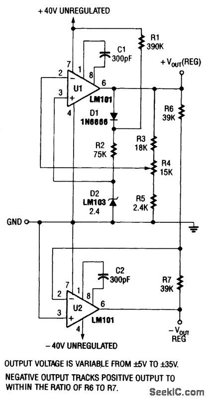
This supply is designed to operate from a ±40V nominal unregulated power source (bridge rectifier, etc.). (View)
View full Circuit Diagram | Comments | Reading(739)
SOUND_ACTIVATED_STROBE_TRIP
Published:2009/6/28 20:57:00 Author:Jessie
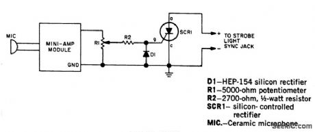
Take strobe-flash pictures the instant a pin pricks a balloon, a hammer breaks a lamp bulb or a bullet leaves a gun. Use a transistor amplifier of 1-watt rating or less. (It must have an output transformer.) The amplifier is terminated with a resistor on its highest output impedance, preferably 16 ohms. To test, darken room lights, open camera shutter, and break a lamp bulb with a hammer. The sound of the hammer striking the lamp will trigger the flash, and the picture will have been taken at that instant. (View)
View full Circuit Diagram | Comments | Reading(1491)
SYNCHRONOUS_STEPDOWN_SWITCHING_REGULATOR_WITH_90%EFFICIENCY
Published:2009/6/26 5:01:00 Author:May
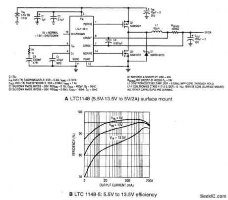
A shows a typical LTC1148 surface-mount application providing 5 V at 2 A from an input voltage of 5.5 V to 13.5 V. The operating efficiency, shown in B, peaks at 97% and exceeds 90% from 10 mA to 2 A with a 10-V input. Q1 and Q2 comprise the main switch and synchronous switch, respectively, and inductor current is measured via the voltage drop across the current shunt. RSENSE is the key component used to set the output current capability according to the formuta IOUT = 100 mV/RSENSE. The advantages of current control include excellent line and load transient rejection, inherent shortcircuit protection and controlled startup currents. Peak inductor current is limited to 150 mV/RSENSE or 3 A for the circuit in A. (View)
View full Circuit Diagram | Comments | Reading(692)
SOUND_LIGHT_FLASH_TRIGGER
Published:2009/6/28 20:55:00 Author:Jessie
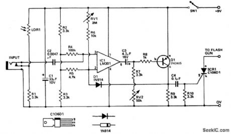
Sound input to the microphone triggers tthe IC monostable circuit which subsequently triggers an SCR, and hence the flash, after a time delay. This delay is adjustable—by varying the monostable on-time—from from 5 milliseconds to 200 milliseconds. (View)
View full Circuit Diagram | Comments | Reading(2364)
REGULATOR_LOSS_CUTTER
Published:2009/6/26 4:55:00 Author:May
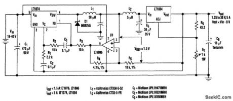
Large input-to-output voltage differentials, caused by wide input voltage variations, reduce a linear regulator's efficiency and increase its power dissipation. A switching preregulator can reduce this power dissipation by minimizing the voltage drop across an adjustable linear regulator to a constant 1.5-V value.
The circuit operates the LT1084 at slightly above its dropout voltage. To rninimize power dissipation, a low-dropout linear reg-ulator was chosen. The LT1084 functions as a conventional adjustable linear regulator with an output voltage that can be varied from 1.25 to 30 V.
Without the preregulator (for a 40-V input and a 5-V output at 5 A), it would be virtually impossible to find a heatsink large enough to dissipate enough energy to keep the linear-regulator junction temperature below its maximum value. With the prereg-ulator technique, however, the linear regulator will dissipate only 7.5 W under worst-case loading conditions for the entire input-voltage range of 15 to 40 V. Even under a short-circuit fault condition, the 1.5-V drop across the LT1084 is maintained. (View)
View full Circuit Diagram | Comments | Reading(2308)
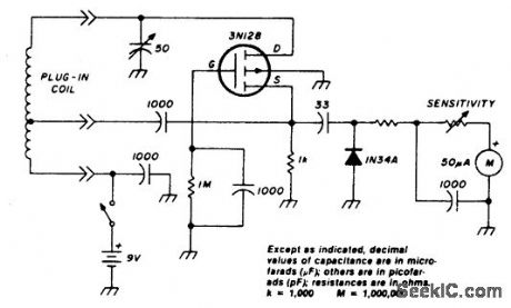
DIP_METER_USING_N_CHANNEL_IGFET(MOSFET)AND_SEPARATE_DIODE_DETECTOR
Published:2009/6/26 4:46:00 Author:May
View full Circuit Diagram | Comments | Reading(758)
DIODELESS_RECTIFIER
Published:2009/6/26 4:39:00 Author:May
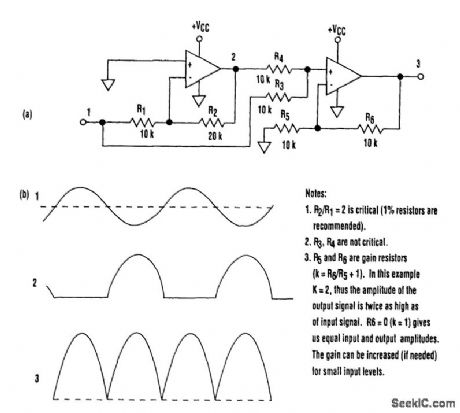
It's common knowledge that when working with single-supply op amps, implementing simple functions in a bipolar signal environment can be difficult. Sometimes additional op amps and other electronic components are required.
Taking that into consideration, can any advantage be attained from this mode? The answer lies in this simple circuit (A). Requiring no diodes, the circuit is a high-precision full-wave rectifier with a high-frequency limitation equalling that of the op amps themselves. Look at the circuit's timing diagram (B) to see the principle of operation.
The first amplifier rectifies negative input Ievels with an inverting gain of 2 and tums positive levels to zero. The second amp, a noninverting surnrning amplifier, adds the inverted negative signal from the first amplifier to the original input signal. The net result is the traditional waveform produced by full-wave rectification.
In spite of the lirnitation on the input signal amplitude (it must be less than VCC/2), this circuit can be useful in a variety of setups. (View)
View full Circuit Diagram | Comments | Reading(1333)
DUAL_AUDIO_AMPLIFIER_POWER_SUPPLY
Published:2009/6/26 4:30:00 Author:May
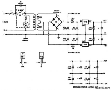
A dual audio amplifier that will deliver 50 W per channel is shown in the schematic. It includes preamp and tone controls, and also includes a headphone amplifier. The circuit depicts the power supply that supplies ±38.5 V and ±15 V regulated for the dual 50 watter. (View)
View full Circuit Diagram | Comments | Reading(2402)
| Pages:1281/2234 At 2012811282128312841285128612871288128912901291129212931294129512961297129812991300Under 20 |
Circuit Categories
power supply circuit
Amplifier Circuit
Basic Circuit
LED and Light Circuit
Sensor Circuit
Signal Processing
Electrical Equipment Circuit
Control Circuit
Remote Control Circuit
A/D-D/A Converter Circuit
Audio Circuit
Measuring and Test Circuit
Communication Circuit
Computer-Related Circuit
555 Circuit
Automotive Circuit
Repairing Circuit