
Circuit Diagram
Index 1290
DC_MOTOR_SPEED_CONTROL
Published:2009/6/25 23:47:00 Author:May
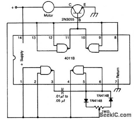
The circuit uses a 4011 CM0S NAND gate, a pair of diodes and an NPN power transistor to provide a variable duty-cycle dc source. Adjusting the speed control varies the average voltage applied to the motor. The peak voltage, however, is not changed. This pulse power is effective at very low speeds, constantly kicking the motor along. At higher speeds, the motor behaves in a nearly normal manner. (View)
View full Circuit Diagram | Comments | Reading(1983)
3_ANTENNA_REMOTE_SWITCHING
Published:2009/6/25 23:46:00 Author:May
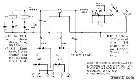
Single RF feed line serves for feeding transmitter power to tower and selecting desired one of three an-tennas. With S1 at a, neither K1 nor K2 is energized. RF energy then passes through cable to antenna terminals a' and GND. In position b,positive half-waves from 12-VAC supply operate relay K1 through CP1 and CR3, so antenna b' is energized. With S1 at c, K2 is energized through CR4 and CR2 forfeeding c'.-U. H. Lam-mers, A Remote Antenna Switch, QST, Aug.1974, p 41-43. (View)
View full Circuit Diagram | Comments | Reading(853)
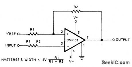
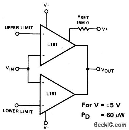
LEVEL_DETECTOR_WITHHYSTERESIS(POSITIVE_FEEDBACK)
Published:2009/6/25 23:46:00 Author:May
View full Circuit Diagram | Comments | Reading(592)
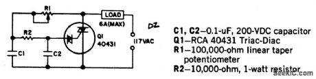
INDUCTION_MOTOR_CONTROL
Published:2009/6/25 23:45:00 Author:May
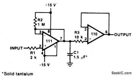
This single time-constant circuit can be used as proportional speed control for induction motors such as shaded pole or permanent split-capacitor motors when the load is fixed. The circuit is best suited to applications which require speed control in the medium to fullpower range. (View)
View full Circuit Diagram | Comments | Reading(1811)
MODEL_TRAIN_SPEED_CONTROL
Published:2009/6/25 23:44:00 Author:May
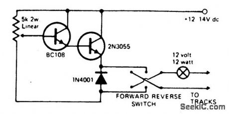
Virtually any NPN small signal transistor may be used in place of the BC 108 shown.Likewise any suitable NPN power transistor can be used in place of the 2N3055. The output transistor must be mounted on a suitable heat-sink. Short circuit protection may be provided by wiring a 12 volt 12 watt bulb in series with the output. This will glow in event of a short circuit and thus effectively current-limit the output, it also acts as a visual short-circuit alarm. (View)
View full Circuit Diagram | Comments | Reading(2270)
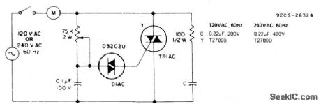
2MOTOR_SPEED_CONTROL
Published:2009/6/25 23:43:00 Author:May
Universal motors and shaded-pole induction motors can be easily controlled with a full-wave Triac speed controller. Q1 combines both the triac and diac trigger diodes in the same case. The motor used for the load must be limited to 6 amperes maximum. Triac Q1 must be provided with a heat sink. With the component values shown, the Triac controls motor speed from full off to full on. (View)
View full Circuit Diagram | Comments | Reading(1652)
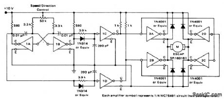
SERVO_MOTOR_AMPLIFIER
Published:2009/6/25 23:42:00 Author:May
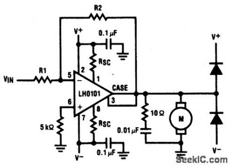
Motor driver amplifier will deliver the rated current into the motor. Care should be taken to keep power dissipation within the permitted level. This precision speed regulation circuit employs rate feedback for constant motor current at a given input voltage. (View)
View full Circuit Diagram | Comments | Reading(845)
PRECISION_FULL_WAVE_RECTIFIER
Published:2009/6/25 23:42:00 Author:May
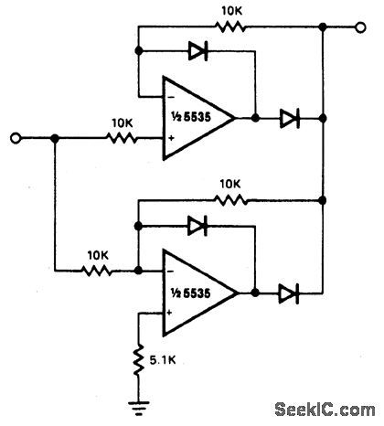
Circuit Notes
The circuit provides accurate full wave rectification. The output impedance is low for both input polarities, and the errors are small at all signal levels. Note that the output will not sink heavy current, except a small amount through the 10 K resistors. Therefore, the load applied should be referenced to ground or a negative voltage. Reversal of all diode polarities will reverse the polarity of the output. Since the outputs of the amplifiers must slew through two diode drops when the input polarity changes, 741 type devices give 5% istortion at about 300 Hz. (View)
View full Circuit Diagram | Comments | Reading(0)
DC_MOTOR_SPEED/DIRECTION_CONTROL_CIRCUIT
Published:2009/6/25 23:41:00 Author:May
View full Circuit Diagram | Comments | Reading(775)
UNIVERSAL_MOTOR_SPEED_CONTROL_WITH_LOAD_DEPENDENT_FEEDBACK(FOR_MIXER,SEWING_MACHINE,ETC)
Published:2009/6/25 23:40:00 Author:May
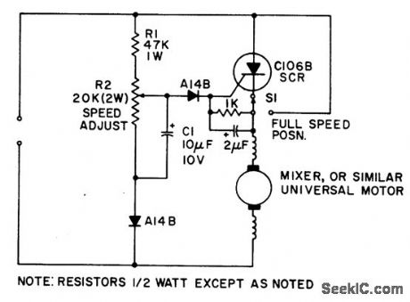
Simple half-wave motor speed control is effective for use with small universal (ac/dc) motors. Maximum current capability 2.0 amps RMS. Because speed-dependent feedback is provided, the control gives excellent torque characteristics to the motor, even at low rotational speeds. Normal operation at maximum speed can be achieved by closing switch S1, thus bypassing the SCR. (View)
View full Circuit Diagram | Comments | Reading(0)
AC_MOTOR_BRAKE
Published:2009/6/25 23:37:00 Author:May

A shot of direct current will instantly stop any ac power tool motor. Switch S1 is a center-off, one side spring return. With S1 on, ac will be fed to the motor and the motor will run. To brake the motor, simply press S1 down and a quick shot of dc will instantly stop it. The switch returns to the center off position when released. This Power Brake can only be used with ac motors; it will not brake universal (ac-dc) motors. A heat sink must be provided for the diode. (View)
View full Circuit Diagram | Comments | Reading(0)
FM_DEMODULAT0_R_AT_12_V__
Published:2009/6/25 23:28:00 Author:May

View full Circuit Diagram | Comments | Reading(0)
80_METER_DIRECT_CONVERSION
Published:2009/6/25 23:28:00 Author:May
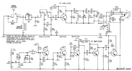
Portabl e receiver with directional ferrod antenna and ver-tical sense antenna was developed for radio foxhunting at 1975 Bov Scout World Jamboree in Norway, in competitions for locating four low-power crystal-controlled transmitters hid-den along 4-km course. Varactor-tuned oscillator provides 20-kHz tuning range with R9, ade-quate for the frequency used-3.566, 3.585, 3.635, or 3680 MHz. T1 is subminiature auto-transformer with 8-ohm and 2000-ohm sec-tions, for 8-ohm headphones. For high-imped-ance headphones, connect headphone jack J1 to lug 9 of T1. ON/OFF switch is not needed, L1 is 22 turns No. 28 enamel wound over two 10×95 mm ferrite rodstaped together. 01-06 are NPN high-frequency small-signal transistors.-N. K. Holter, Radio Foxhunting in Europe, QST, Nov. 1976, p 43-46. (View)
View full Circuit Diagram | Comments | Reading(0)
5_STEP_ATTENUATOR
Published:2009/6/25 23:27:00 Author:May

AppIication s indude comparing performance of various rece Mng an-tennas and measuring gain of preamp used abead of receiver. Dashed lines represent required shield partitions. All resistors are 1/4-W composition with 5% tolerance.-D.DeMaw, What Does My S-Meter Tell Me?, QST,June 1977,p 40-42. (View)
View full Circuit Diagram | Comments | Reading(0)
RF_BRIDGE_FOR_COAX
Published:2009/6/25 23:27:00 Author:May
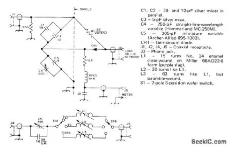
Simplifies adjustment of vertical antenna for 40, 80, and 160 meters.S1 in add-on LC unit switches coil for desited band. Values of C1-C4 and standard resistor R1 give range of 10 to 150 ohms for measurement of radiation resistance. Meter can be from 50 to 200μA full scale if 500 mW of power is available as signal source. For shorter-wavelength bands, change resistance in parallel with J1 to 5600 ohms and omit C6. L1 for 10 meters should then have 3 1/2 tums No. 18 spaced to occupy 1/4 inch on Miller4200 coilform. L2(15 meters) is Gtums No. 16 enamel closewound on similar form. L3 (20 meters) is 11 turns No.14 enamel on Miller 66A022-6 form.-J. Sevick, Simple RF Bridges, OST, April 1975, p 11-16 and 41. (View)
View full Circuit Diagram | Comments | Reading(0)
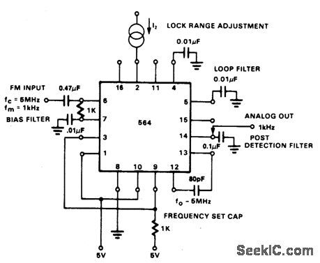
FM_DEMODULATOR_AT_5_V__
Published:2009/6/25 23:26:00 Author:May
View full Circuit Diagram | Comments | Reading(0)
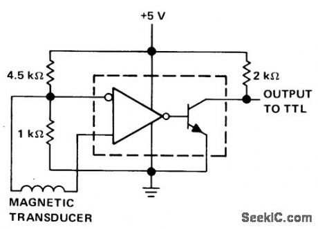
DETECTOR_FOR__MAGNETIC_TRANSDUCER___
Published:2009/6/25 23:22:00 Author:May
View full Circuit Diagram | Comments | Reading(0)
SWR_COMPUTER
Published:2009/6/25 23:20:00 Author:May

Au tomatlcally computos standing+ave ratio in 50-ohm coax feeding an tenna and delivers analog voltage for ddving meter or digital display. Inputs are forward (VFIN) and reverse (VRIN) voltages as convention-ally measured for SWR checks. Requires regu Iated ±15 VDC supply at 40 mA. Article gives construction details and covers adjustment of critical resistors during alignment.-T.May-hugh, A Digital SWR Computerl, 73 Magazine, Nov 1974, p 80-82,84, and 86. (View)
View full Circuit Diagram | Comments | Reading(0)
SELF_EXCITED_SWR_BRlDGE
Published:2009/6/25 23:19:00 Author:May

Portable bridge has built-in signal sources for each band from 80 through 10 meters, for tuning antenna on tower before transmission line is connected.Oscillators are crystal controlled at desired antenna tuneup frequencies. Separate oscillators for each band simplify switching problems, so only supply voltage from J1 and oscillator outputs to meter circuit need be switched. Current drain from 9-V battery is maximum of 12 mA.R17 and R18 should be closely matched, while R1, and R20 should have 5% tolerance.-T.P.Hulick, An S.W.R.Bridge with a Built-In 80 Through 10 Meter Signal Source, CQ1 June 1971,p 64-66 68, and 99. (View)
View full Circuit Diagram | Comments | Reading(0)
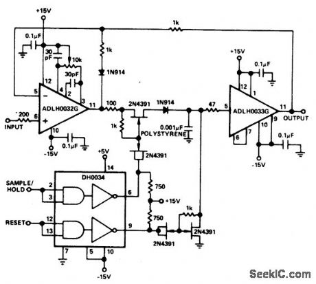
HIGH_SPEED_PEAK_DETECTOR
Published:2009/6/25 23:19:00 Author:May
View full Circuit Diagram | Comments | Reading(859)
| Pages:1290/2234 At 2012811282128312841285128612871288128912901291129212931294129512961297129812991300Under 20 |
Circuit Categories
power supply circuit
Amplifier Circuit
Basic Circuit
LED and Light Circuit
Sensor Circuit
Signal Processing
Electrical Equipment Circuit
Control Circuit
Remote Control Circuit
A/D-D/A Converter Circuit
Audio Circuit
Measuring and Test Circuit
Communication Circuit
Computer-Related Circuit
555 Circuit
Automotive Circuit
Repairing Circuit