
Circuit Diagram
Index 1282
DUAL_VOLTAGE_RECTIFIER_CIRCUIT
Published:2009/6/26 4:27:00 Author:May
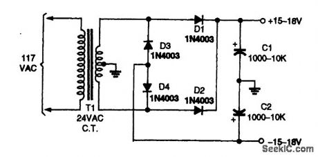
This stepped-up dual voltage supply provides ±15 to ±18V unregulated. (View)
View full Circuit Diagram | Comments | Reading(844)
VHF_PREAMPLIFIER
Published:2009/6/26 4:27:00 Author:May
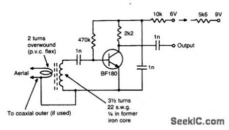
This simple circuit gives 15 dB gain and can be mounted on 1 in 2PCB. Coil data is given for 85 to 95 MHz. For other frequencies modify coil as required. (View)
View full Circuit Diagram | Comments | Reading(755)
SHORTWAVE_FET_BOOSTER
Published:2009/6/26 4:26:00 Author:May
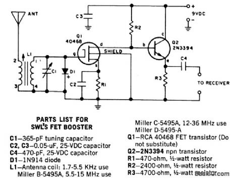
This two transistor preselector provides up to 40 dB gain from 3.5 to 30 MHz. Q1 (MOSFET) is sensitive to static charges and must be handled with care. (View)
View full Circuit Diagram | Comments | Reading(1168)
SINGLE_TRANSISTOR_PHASE_SHIFTER
Published:2009/6/28 20:40:00 Author:Jessie
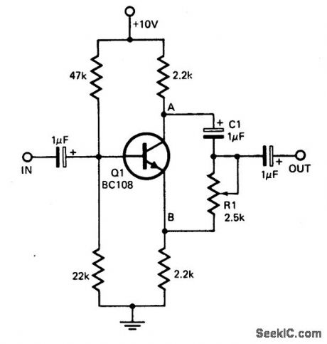
This circuit provides a simple means of obtaining phase shifts between zero and 170°.The transistor operates as a phase splitter, the output at point A being 180° out of phase with the input. Point B is in phase with the input phase. Adjusting R1 provides the sum of various proportions of these and hence a continuously variable phase shift is provided. The circuit operates well in the 600 Hz to 4 kHz range. (View)
View full Circuit Diagram | Comments | Reading(0)
SUBWOOFER_AMPLIFIER_POWER_SUPPLY
Published:2009/6/26 4:26:00 Author:May
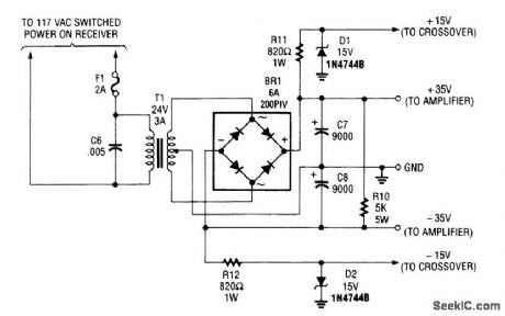
Although intended to power a 100-W low-frequency amplifier, this power supply should handle many mono or stereo amplifiers in the medium power range that require ±30 to 35 V. (View)
View full Circuit Diagram | Comments | Reading(996)
lO_MHz_COAXIAL_LINE_DRIVER
Published:2009/6/26 4:22:00 Author:May

The circuit will find excellent usage in high frequency line driving systems that re-quire wide-power bandwidths at high output current levels. (IC = HA2530) The bandwidth of the circuit is limited only by the single pole response of the feedback components; namely f(-3 dB) = 1/2 πRfCf. As such, the response is flat with no peaking and yields minimum distortion. (View)
View full Circuit Diagram | Comments | Reading(878)
PHASE_SEQUENCE_INDICATOR
Published:2009/6/28 20:39:00 Author:Jessie
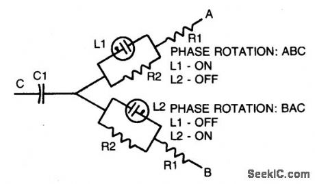
Simple, portable phase-sequence indicator determines the proper phase rotation in polyphase circuits. Major components are two neon lamps, two resistors, and a capacitor. In operation, the leg voltages are unbalanced, so that the lamp with the maximum voltage—or proper phase sequence—lights. Table shows typical component values for various circuit frequencies. (View)
View full Circuit Diagram | Comments | Reading(0)
ac_VOLTAGE_PROBE
Published:2009/6/26 5:32:00 Author:Jessie
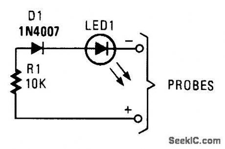
This simple probe can save your life by waming you of live circuitry. It's ideal for times when more than one person is working on a device. (View)
View full Circuit Diagram | Comments | Reading(0)
SIMPLE_VOLTAGE_PROBE
Published:2009/6/26 5:31:00 Author:Jessie
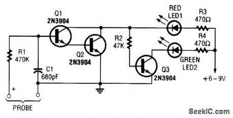
This simple voltage probe can be helpful in checking and troubleshooting solid-state circuitry. (View)
View full Circuit Diagram | Comments | Reading(0)
TELECOM_CONVERTER_-48_V_TO_5_V@1_A
Published:2009/6/26 5:29:00 Author:Jessie

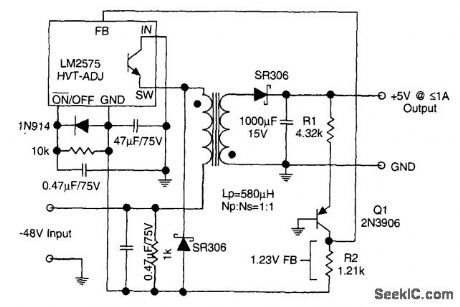
The circuit supplies 1 A at +5 V from the -48-V supply commonly used in telephone equipment. The National Semiconductor LM2575 is a simple switching regulator. (View)
View full Circuit Diagram | Comments | Reading(1301)
ADD_12_V_OUTPUT_TO_5_v_BUCK_REGULATOR
Published:2009/6/26 5:27:00 Author:Jessie
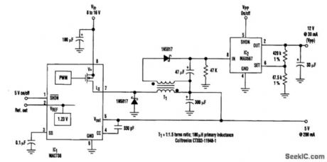
By adding a flyback winding to a buck-regulator switching converter (see the figure), which is essentially a 5-V supply with a 200-mA output capability, a 12-V output (VPP) can be produced. The flyback winding on the main inductor (forming transformer T1) enables an additional low-dropout linear regulator (IC2) to create the 12-V output voltage that's needed to program EEPROMs. The required input voltage is 8 to 16 V. (View)
View full Circuit Diagram | Comments | Reading(828)
24_V_TO_33_V_SWITCHING_REGULATOR
Published:2009/6/26 4:08:00 Author:May
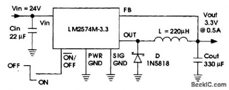
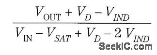
The National Semiconductor LM2574 delivers 3.3 V out at O.SAfrom a 24-V source. The duty cycle is:VD = diode drop(0.39)VIND = inductor dc dropVSAT = saturation voltage of LM2574(0.9 V typical) (View)
View full Circuit Diagram | Comments | Reading(0)
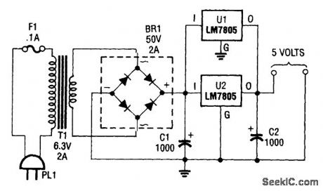
_5_V_SUPPLY
Published:2009/6/26 5:24:00 Author:Jessie

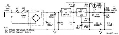
The power supply shown is designed to operate from a wall transformer. This circuit can be used in conjunction with a variable supply to test circuits in the lab, etc. T2 is a 12-V wall transformer. (View)
View full Circuit Diagram | Comments | Reading(805)
AUDIO_CONTINUITY_TESTER
Published:2009/6/26 4:05:00 Author:May
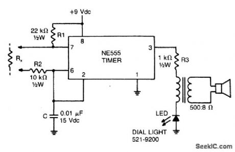
This low-current audio continuity tester indicates the unknown resistance value by the frequency of audio tone. A high tone indicates a low resistance, and a tone of a few pulses per second indicates a resistance as high as 30 megohms. (View)
View full Circuit Diagram | Comments | Reading(0)
5_V_UPS
Published:2009/6/26 5:22:00 Author:Jessie
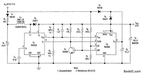
A 9-V wall adapter supplies VIN. IC2 contains a low-battery detector circuit that senses VIN by means of R6 and R7. The detector output (pin 7) drives an inverter (Q1), which in tum drives the shut-down inputs IC of IC1 and SHDN of IC2. These inputs have opposite-polarity active levels. The common feedback resistors, R2 and R3 enable both regulators to sense the output voltage, VOUT.
When IC2 shuts down, its output turns off. However, when IC1 shuts down, the whole chip assumes a low-power state and draws under 1 μA. L1, D2, C1, C2, R2, and R3 are part of the 250-mW switching regulator. Diodes D3 and D4 wire-OR the power connection to IC2, and C3 improves the linear regulator's load regulation. (View)
View full Circuit Diagram | Comments | Reading(1773)
5_V_TO_33_V_SWITCHING_REGULATOR
Published:2009/6/26 4:05:00 Author:May
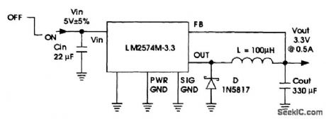
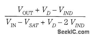
A National Semiconductor LM2574 is used to derive 3.3 V at 0.5 A from a 5-V logic bus. The duty cycle is: VD = diode drop (0.39) VIND = inductor dc drop VSAT = saturation voltage of LM2574 (0.9 V typical) This circuit should be useful to derive 3.3 V for logic devices from existing +5-V buses. (View)
View full Circuit Diagram | Comments | Reading(0)
INEXPENSIVE_ISOLATION_TRANSFORMERIMPROMPTU_SETUP
Published:2009/6/26 5:17:00 Author:Jessie
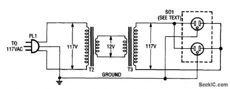
Using two 12-V filament or power transformers, an impromptu isolation transformer can be made for low-power(under 50 W) use in testing or servicing. SO1 is an ordinary, duplex ac receptable. Use heavy-wire connections between the 12-V windings because several amperes can flow. (View)
View full Circuit Diagram | Comments | Reading(3490)
LOW_PARTS_COUNT_RATIOMETRIC_RESISTANCE_MEASUREMENT
Published:2009/6/26 4:04:00 Author:May
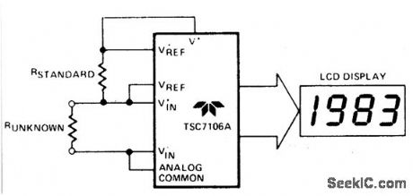
The unknown resistance is put in series with a known standard and a current passed through the pair. The voltage developed across the unknown is applied to the input and the voltage across the known resistor applied to the reference input. If the unknown equals the standard, the display will read 1000. The dis-played reading can be determined from the following expression:Runknown
Displayed Reading= ___________ =×1000 RstandardThe display will overrange for Runknown, ≥2× Rstandard. (View)
View full Circuit Diagram | Comments | Reading(0)
ANTIQUE_RADIO_dc_FILAMENT_SUPPLY
Published:2009/6/26 5:11:00 Author:Jessie
This dc supply is great for operattng battery-powered anuque radios, because it is designed to prevent harming the tube filaments. The circuit is useful for powenng filaments of 00-A, 01-A, 112A,and 71A tubes, which requlre 5V at 250 mA. (View)
View full Circuit Diagram | Comments | Reading(1009)
_15_V_SUPPLY_FOR_ZN416E_CIRCUITS
Published:2009/6/26 5:07:00 Author:Jessie
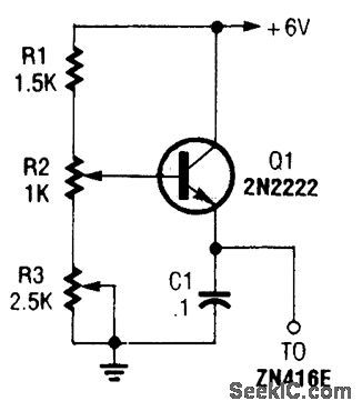
This regulator can be used with a +6-V source to supply ZN416E low-voltage TRF radio-receiver IC the necessary +1.5 V. R3 sets output voltage. (View)
View full Circuit Diagram | Comments | Reading(731)
| Pages:1282/2234 At 2012811282128312841285128612871288128912901291129212931294129512961297129812991300Under 20 |
Circuit Categories
power supply circuit
Amplifier Circuit
Basic Circuit
LED and Light Circuit
Sensor Circuit
Signal Processing
Electrical Equipment Circuit
Control Circuit
Remote Control Circuit
A/D-D/A Converter Circuit
Audio Circuit
Measuring and Test Circuit
Communication Circuit
Computer-Related Circuit
555 Circuit
Automotive Circuit
Repairing Circuit