
Circuit Diagram
Index 1292
TEMPERATURE_CONTROLLER_2
Published:2009/6/25 23:19:00 Author:Jessie
View full Circuit Diagram | Comments | Reading(652)
SELF_EXCITED_SWR_BRlDGE
Published:2009/6/25 23:19:00 Author:Jessie
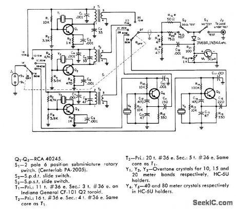
Portable bridge has built-in signal sources for each band from 80 through 10 meters, for tuning antenna on tower before transmission line is connected.Oscillators are crystal controlled at desired antenna tuneup frequencies. Separate oscillators for each band simplify switching problems, so only supply voltage from J1 and oscillator outputs to meter circuit need be switched. Current drain from 9-V battery is maximum of 12 mA.R17 and R18 should be closely matched, while R1, and R20 should have 5% tolerance.-T.P.Hulick, An S.W.R.Bridge with a Built-In 80 Through 10 Meter Signal Source, CQ1 June 1971,p 64-66 68, and 99. (View)
View full Circuit Diagram | Comments | Reading(1264)
TEMPERATURE_CONTROLLER
Published:2009/6/25 23:09:00 Author:May
View full Circuit Diagram | Comments | Reading(0)
CONSTANT_CURRENT_MOTOR_DRIVE_CIRCUIT
Published:2009/6/25 23:07:00 Author:May
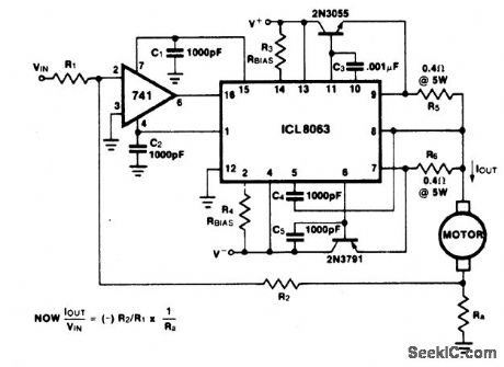
This minimum device circuit can be used to drive dc motors where there is some like lihood of stalling or lock up; if the motor locks, the current drive remains constant and the system does not destroy itself. (View)
View full Circuit Diagram | Comments | Reading(916)
1MOTOR_SPEED_CONTROL
Published:2009/6/25 23:06:00 Author:May
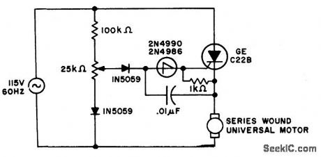
Switching action of the 2N4990 allows smaller capacitors to be used while achieving reliable thyristor triggering. (View)
View full Circuit Diagram | Comments | Reading(919)
HALF_WAVE_RECTIFIER
Published:2009/6/25 23:06:00 Author:May
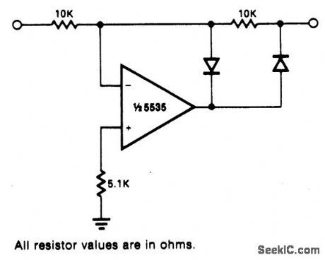
Circuit Notes
This circuit provides for accurate half wave rectification of the incoming signal. For positive signals, the gain is 0; for negative signals, the gain is -1. By reversing both di-odes, the polarity can be inverted. This circuit provides an accurate output, but the output impedance differs for the two input polarities and buffering may be needed. The output must slew through two diode drops when the input polarity reverses. The NE5535 device will work up to 10 kHz with less ttan 5% distortion. (View)
View full Circuit Diagram | Comments | Reading(0)
PULSE_BASELINE_CLAMP
Published:2009/6/25 22:01:00 Author:May
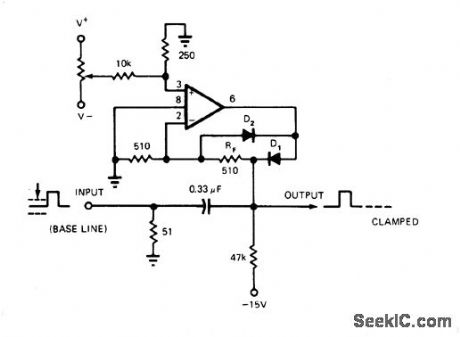
Provides accurate clamping of baseline level of fast positive-going digital pulses with constantly changing duty cycle when capacitively coupled into level-sensitive circuits. Uses HA-2535 opamp. Diode D2 clamps negative output swing of opamp to about 0.3V, preserving amplifier recovery time in preparation for clamping next input transition, Pulse widths at input are less than 100 ns, with transition time under 15 ns and duty cycle ranging from 2 to 50%. Diodes are HP 2800 series. For clamping sine or triangle AF waves, opamp can be 741.-D. L. Quick, Clamp Speeds Restoration of AC-Coupled Base Lines, EDN Magazine, Sept. 5,1975, p 76. (View)
View full Circuit Diagram | Comments | Reading(1639)
DOUBLE_ENDED_LIMIT_DETECTOR
Published:2009/6/25 23:04:00 Author:Jessie
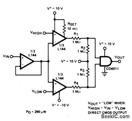
Circuit NotesDetector uses three sections of an L144 and a CM0S NAND gate to make a very low power voltage monitor. The 1 MO resistors R1, R2, R3, and R4 translate the bipolar t10 V swing of the op amps to a 0 to 10 V swing acceptable to the ground-referenced CMOS logic. The total power dissipation is 290 ptW while in limit and 330 ;tW while out of limit. (View)
View full Circuit Diagram | Comments | Reading(0)
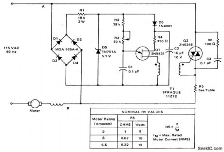
HIGH_TORQUE_MOTOR_SPEED_CONTROL
Published:2009/6/25 23:04:00 Author:Jessie
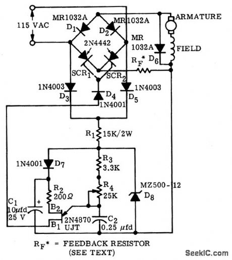


A bridge circuit consisting of two SCRs and two silicon rectifiers furnishes full-wave opower to the motor.Diodes,D3 and D5,supply dc to the trigger circuit through dropping reslstors,R1.Phase delay of SCR firing is obtained by charging C2 through resistors R3 and R4 from the voltage level established by the zener dione,D8.When C2 charges to the firing voltage of the unijunction transistor,the UJT fires,triggering the SCR that has a positive on its anode,When C2 discharges sufficiently,the unijunction transistor drops out of conduction.The value of RF is dependent upon the size of the motor and on the amount of feedback desired.A typical value for RF can be calculated from: RF=-2/IM where SIM is the max rated load current(rms)。 (View)
View full Circuit Diagram | Comments | Reading(1731)
DVM_FOR_SWR
Published:2009/6/25 23:00:00 Author:Jessie


Converts voltage output from analog computer to drive for 3-digit LED display of standing-wave ratio. Circuit uses Precision Monolithics D/A converter AIMDAC-100CC-Q1.Requires regulated 5-VDC logic supply at 1A for digital display, along with ±15V supplies for logic. Article gives alignment procedure. Accuracy of digital reading is better than 0.1% over 0-8 V range.-T.Mayhugh, The Automatic SWR Computer, 73Magazine, Dec.1974, p 86-87 (View)
View full Circuit Diagram | Comments | Reading(921)
ANTENNA_ROTATOR
Published:2009/6/25 22:59:00 Author:Jessie
Two-opamp Wheatstone bridge provides positive and negative error signals to give proportional control for 24-VDC motor used for remote positioning of an tenna. Circuit will operate with supply ranging from 15 to 28 VDC. Off set null controls for opamps use 10K pots. Article describes opera-tion and adjustment of circuit in detail, -D.J.Telfer, An Aerial Rotator Servo, Wireless World, April1975, p 177-181. (View)
View full Circuit Diagram | Comments | Reading(1852)
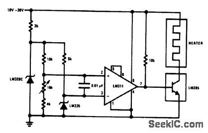
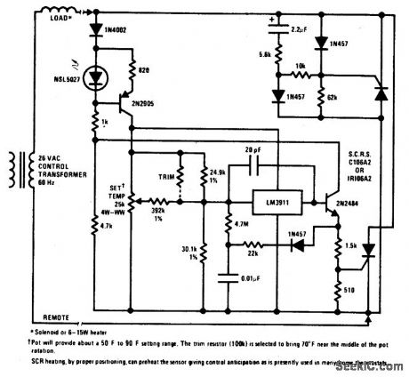
TEMPERATURE_SENSITIVE_HEATER_CONTROL
Published:2009/6/25 22:58:00 Author:Jessie

View full Circuit Diagram | Comments | Reading(745)
THREE_WIRE_ELECTRONIC_THERMOSTAT
Published:2009/6/25 22:56:00 Author:Jessie
View full Circuit Diagram | Comments | Reading(796)
LADDER_ATTENUATOR
Published:2009/6/25 22:51:00 Author:May
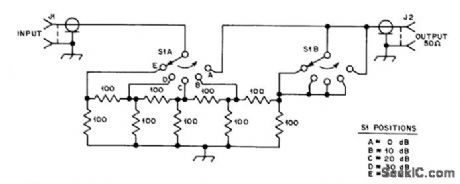
Inserted in series with receiving antenna to provide 5 steps of attenuation for comparing performance of anten-nas or preamps. Resistors are 1/4-W composition with 5% tolerance.-D. DeMaw, What Does My S-Meter Tell Me?, QST, June 1977, p 40-42. (View)
View full Circuit Diagram | Comments | Reading(0)
TWO_WIRE_REMOTE_AC_ELECTRONIC_THERMOSTAT(GAS_OR_OIL_FURNACE_CONTROL)
Published:2009/6/25 22:55:00 Author:Jessie
View full Circuit Diagram | Comments | Reading(765)
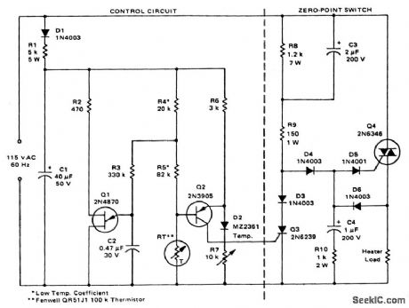
HEATER_CONTROL
Published:2009/6/25 22:54:00 Author:Jessie
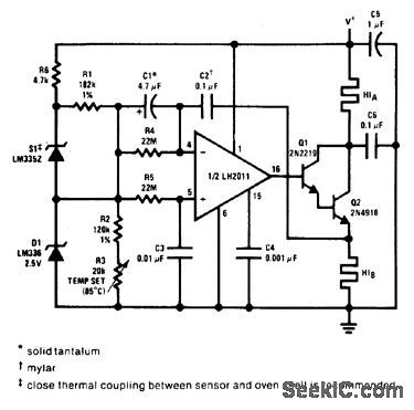
This proportional control crystal oven heater uses lead/lag compensation for fast set-ting. The time constant is changed with R4 and compensating resistor R5. If Q2 is inside the oven, a regulated supply is recommended for 0.1 ℃. control. (View)
View full Circuit Diagram | Comments | Reading(1350)
TWO_ROTATOR_CONTROL
Published:2009/6/25 22:52:00 Author:Jessie
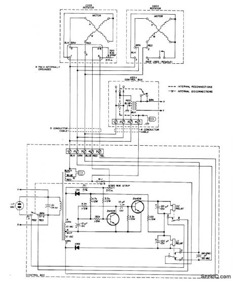
Low-cost Alliance C-225 TV antenna rotator and Alliance K22A ro-tator with control box are used with single tran-sistorized-bridge control circuit. Rotators op-erate in tandem on same shaft to provide double torque for handling medium-size 20-meter amateur radio antennas. One arm of bridge is 520-ohm wirewound pot in which wiper position is proportional to heading. Artiole covers wiring and bench-testing of rotators.-F.E.Gehrke,Antenna Rotator for Medium-sized Beams,Ham Radio,May 1976、p48-51. (View)
View full Circuit Diagram | Comments | Reading(4118)
DELAYED_BRAKE
Published:2009/6/25 22:48:00 Author:May
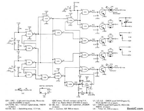
Protects antenna rotator on high tower from damage by delaying brake ac-tion automatically after rotation and by disa-bling direction-selector switches so antenna system coasts to stop before rotation can begin in other direction. For about 3.s delay in timer U4, use 2.2 megohms for R and 1μF for C instead of values shown. RV1 is commonly listed as V150LA20A by GE.S3-S5 are original brake release and direction switches in CDE Hamllrotor system,Article coners construction and installation, including modifications needed Incontrol unit.-A.B,White,A Delayed Brake Release for the Ham-ll,QST, Aug.1977、p14- 16 (View)
View full Circuit Diagram | Comments | Reading(0)
FULL_WAVE_RECTIFIER_AND_AVERAGING_FILTER
Published:2009/6/25 22:45:00 Author:May
View full Circuit Diagram | Comments | Reading(660)
MOTOR_SPEED_CONTROL_WITH_FEEDBACK
Published:2009/6/25 22:45:00 Author:May
View full Circuit Diagram | Comments | Reading(729)
| Pages:1292/2234 At 2012811282128312841285128612871288128912901291129212931294129512961297129812991300Under 20 |
Circuit Categories
power supply circuit
Amplifier Circuit
Basic Circuit
LED and Light Circuit
Sensor Circuit
Signal Processing
Electrical Equipment Circuit
Control Circuit
Remote Control Circuit
A/D-D/A Converter Circuit
Audio Circuit
Measuring and Test Circuit
Communication Circuit
Computer-Related Circuit
555 Circuit
Automotive Circuit
Repairing Circuit