
Circuit Diagram
Index 1291
TEMPEATURE_CONTROLLER
Published:2009/6/25 23:18:00 Author:May
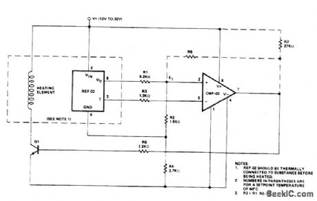
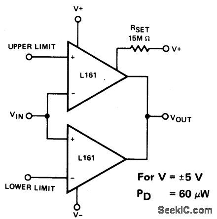
Temperature control is achieved using the REF-02 +5 V Reference/Thermometer and a CMP-02 Precision Low Input Current Com-parator. The CMP-02 turns on a heating ele-ment driver (Q1) whenever the present temperature drops below a setpoint temperature determined by the ratio of RI to R2. The circuit also provides adjustable hysteresis and single supply operation. (View)
View full Circuit Diagram | Comments | Reading(653)
TEMPERATURE_CONTROL
Published:2009/6/25 23:16:00 Author:May
View full Circuit Diagram | Comments | Reading(1127)
MISSING_PULSE_DETECTOR
Published:2009/6/25 23:16:00 Author:May
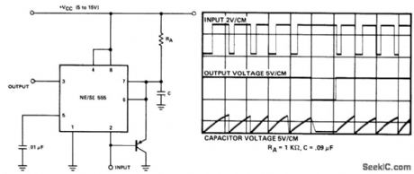
Circuit NotesThe timing cycle is continuously reset by the input pulse train. A change in frequency, or a missing pulse, allows completion of the tim-ing cycle which causes a change in the output level. For this application, the time delay should be set to be slightly longer than the normal time between pulses. The graph shows the actual waveforms seen in this mode of op-eration. (View)
View full Circuit Diagram | Comments | Reading(1)
UNIVERSAL_MOTOR_SPEED_CONTROL_WITH_LOAD_DEPENDENT_FEEDBACK(FOR_MIXER,SEWING_MACHINE,ETC)
Published:2009/6/25 23:40:00 Author:Jessie
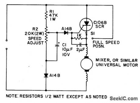
Simple half-wave motor speed control is effective for use with small universal (ac/dc) motors. Maximum current capability 2.0 amps RMS. Because speed-dependent feedback is provided, the control gives excellent torque characteristics to the motor, even at low rotational speeds. Normal operation at maximum speed can be achieved by closing switch S1, thus bypassing the SCR. (View)
View full Circuit Diagram | Comments | Reading(2508)
AC_MOTOR_BRAKE
Published:2009/6/25 23:37:00 Author:Jessie
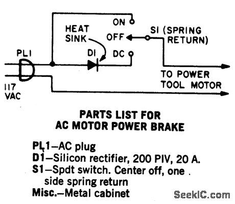
A shot of direct current will instantly stop any ac power tool motor. Switch S1 is a center-off, one side spring return. With S1 on, ac will be fed to the motor and the motor will run. To brake the motor, simply press S1 down and a quick shot of dc will instantly stop it. The switch returns to the center off position when released. This Power Brake can only be used with ac motors; it will not brake universal (ac-dc) motors. A heat sink must be provided for the diode. (View)
View full Circuit Diagram | Comments | Reading(1790)
TEMPERATURE_CONTROLLER_1
Published:2009/6/25 23:15:00 Author:May
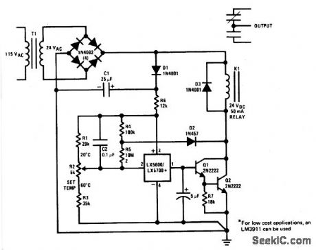
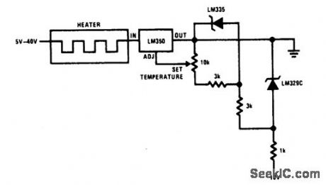
The sensor is a standard TO-5 or TO-46 package. For surface or air temperature sens-ing. Small clip-on heat sinks can be used. A simple probe can be made using heat-shrink tubing and RTV silicon rubber. Three-leads-plus-shield cable is a good choice for wire with the shield connected to pin 4. The controller can be used for baths, ovens, oven-temperature protection, or even home thermostats. Long-term stability and repeatability is better than 0.5 ℃. (View)
View full Circuit Diagram | Comments | Reading(0)
FAR_FIELD_TRANSMITTER
Published:2009/6/25 23:14:00 Author:May
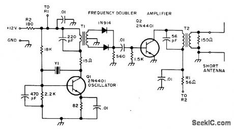
Provides far-field signal source for tuning Yagi and other beam antennas used on amateur radio frequencies.Q1 is Pierce oscillator operating in fundamental mode of 7.06-MHz crystal to permit field-strength measurements at 14.12, 21.18, and 28.24 MHz for 20-, 15-, and 10-meter bands. An-tenna uses two 5-foot lengths of wire con-nected as dipole. T1 is Amidon core 750-2 with 22 tums on primary and 20 tums center-tapped on secondary. T2 is same core with 22-tum pri-mary and 5-tum secondary.-G. Hinkle, Closed Loop Antenna Tuning, 73Magazine, May 1976, p32-33. (View)
View full Circuit Diagram | Comments | Reading(1048)
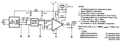
FM_TUNER_WITH_A_SINGLE_TUNED_DETECTOR_COIL
Published:2009/6/25 23:13:00 Author:May
View full Circuit Diagram | Comments | Reading(651)
FM_DEMODULAT0_R_AT_12_V__
Published:2009/6/25 23:28:00 Author:Jessie
View full Circuit Diagram | Comments | Reading(1032)
80_METER_DIRECT_CONVERSION
Published:2009/6/25 23:28:00 Author:Jessie
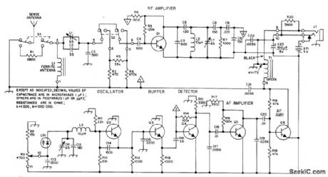
Portabl e receiver with directional ferrod antenna and ver-tical sense antenna was developed for radio foxhunting at 1975 Bov Scout World Jamboree in Norway, in competitions for locating four low-power crystal-controlled transmitters hid-den along 4-km course. Varactor-tuned oscillator provides 20-kHz tuning range with R9, ade-quate for the frequency used-3.566, 3.585, 3.635, or 3680 MHz. T1 is subminiature auto-transformer with 8-ohm and 2000-ohm sec-tions, for 8-ohm headphones. For high-imped-ance headphones, connect headphone jack J1 to lug 9 of T1. ON/OFF switch is not needed, L1 is 22 turns No. 28 enamel wound over two 10×95 mm ferrite rodstaped together. 01-06 are NPN high-frequency small-signal transistors.-N. K. Holter, Radio Foxhunting in Europe, QST, Nov. 1976, p 43-46. (View)
View full Circuit Diagram | Comments | Reading(1436)
SINGLE_SETPOINT_TEMPERATRE_CONTROLLER
Published:2009/6/25 23:13:00 Author:May
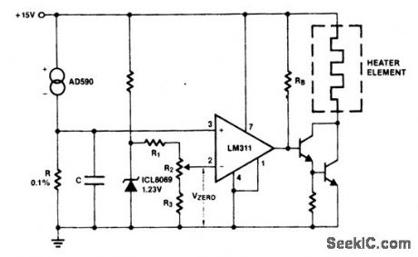
Ths AD590 produces a temperature-dependent voltage across R (C is for filtering noise). Setting R2 produces a scale-zero voltage. For the Celsius scale, make R=1K and Vzero=0.273 volts. For Fahrenheit, R=1.8K and Vzero=0.460 volts. (View)
View full Circuit Diagram | Comments | Reading(686)
VSWR_METER
Published:2009/6/25 23:13:00 Author:May

Simple, easily transported VSWR meter consists of high-gain amplifier, narrow-bandwidth (100-Hz) selective amplifier tuned to 1000 Hz, and variable-gain output amplifier driving low-cost VU meter. Ideal for nulling type VSWR measurements. Draws only about 6mA from 9.V transistor battery. Closing S1 increases gain about 100 times for Iow.Ievel readings. R1 sets U1B to 1000 Hz, while R2 sets reference on VU meter.-J.Reisert Matching Techniques for VHF/UHF Antennas, Ham Fladio,July 1976,p50-56. (View)
View full Circuit Diagram | Comments | Reading(1420)
160_METER_LOOP_PREAMP
Published:2009/6/25 23:12:00 Author:May
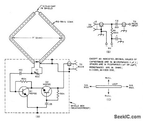
Shielded 5-foot square loop and single preamp pull signals out of noise when propagation conditions make other antennas unsatisfactory. Operating volt-age is supplied through coax feeder, R1 isolates signal energy from ground, and C2 keeps DC voltage out of receiver input. Nulls are off broad side of loop.-B. Boothe, Weak-Signal Recep-tion on 160-Some Antenna Notes, QST, June 1977, p 35-39. (View)
View full Circuit Diagram | Comments | Reading(4267)
5_STEP_ATTENUATOR
Published:2009/6/25 23:27:00 Author:Jessie

AppIication s indude comparing performance of various rece Mng an-tennas and measuring gain of preamp used abead of receiver. Dashed lines represent required shield partitions. All resistors are 1/4-W composition with 5% tolerance.-D.DeMaw, What Does My S-Meter Tell Me?, QST,June 1977,p 40-42. (View)
View full Circuit Diagram | Comments | Reading(1394)
RF_BRIDGE_FOR_COAX
Published:2009/6/25 23:27:00 Author:Jessie
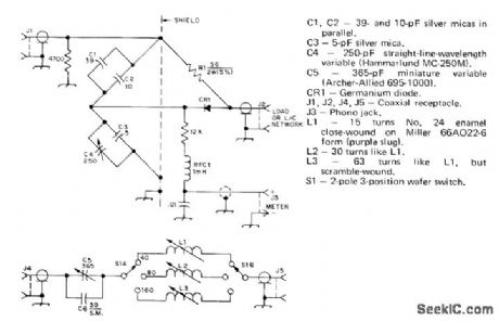
Simplifies adjustment of vertical antenna for 40, 80, and 160 meters.S1 in add-on LC unit switches coil for desited band. Values of C1-C4 and standard resistor R1 give range of 10 to 150 ohms for measurement of radiation resistance. Meter can be from 50 to 200μA full scale if 500 mW of power is available as signal source. For shorter-wavelength bands, change resistance in parallel with J1 to 5600 ohms and omit C6. L1 for 10 meters should then have 3 1/2 tums No. 18 spaced to occupy 1/4 inch on Miller4200 coilform. L2(15 meters) is Gtums No. 16 enamel closewound on similar form. L3 (20 meters) is 11 turns No.14 enamel on Miller 66A022-6 form.-J. Sevick, Simple RF Bridges, OST, April 1975, p 11-16 and 41. (View)
View full Circuit Diagram | Comments | Reading(1696)
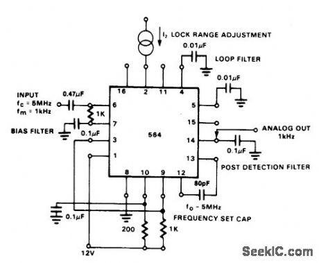
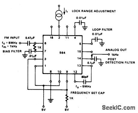
FM_DEMODULATOR_AT_5_V__
Published:2009/6/25 23:26:00 Author:Jessie
View full Circuit Diagram | Comments | Reading(1091)
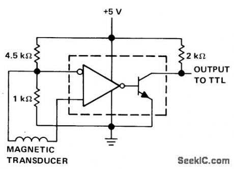
DETECTOR_FOR__MAGNETIC_TRANSDUCER___
Published:2009/6/25 23:22:00 Author:Jessie
View full Circuit Diagram | Comments | Reading(1436)
SWR_COMPUTER
Published:2009/6/25 23:20:00 Author:Jessie
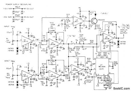
Au tomatlcally computos standing+ave ratio in 50-ohm coax feeding an tenna and delivers analog voltage for ddving meter or digital display. Inputs are forward (VFIN) and reverse (VRIN) voltages as convention-ally measured for SWR checks. Requires regu Iated ±15 VDC supply at 40 mA. Article gives construction details and covers adjustment of critical resistors during alignment.-T.May-hugh, A Digital SWR Computerl, 73 Magazine, Nov 1974, p 80-82,84, and 86. (View)
View full Circuit Diagram | Comments | Reading(1324)
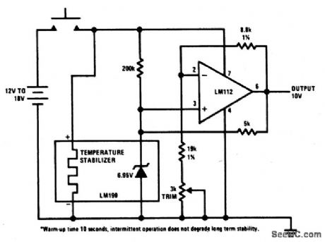
PORTABLE_CALIBRATOR
Published:2009/6/25 23:19:00 Author:Jessie
View full Circuit Diagram | Comments | Reading(621)
TONE_DETECTOR
Published:2009/6/25 23:12:00 Author:May
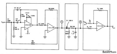
Circuit Notes
The detector circuit is made up a two-amplifier multiple feedback bandpass filter followed by an ac-to-dc detector section and a Schmitt Trigger. The bandpass filter (with a Q of greater than 100) passes only 500 Hz inputs whch are in turn rectified by D1 and filtered by R9 and CA. This filtering action in combination with the trigger level of 5 V for the Schmitt device insures that at least 55 cycles of 500 Hz input must be present before the output will react to a tone input. (View)
View full Circuit Diagram | Comments | Reading(1308)
| Pages:1291/2234 At 2012811282128312841285128612871288128912901291129212931294129512961297129812991300Under 20 |
Circuit Categories
power supply circuit
Amplifier Circuit
Basic Circuit
LED and Light Circuit
Sensor Circuit
Signal Processing
Electrical Equipment Circuit
Control Circuit
Remote Control Circuit
A/D-D/A Converter Circuit
Audio Circuit
Measuring and Test Circuit
Communication Circuit
Computer-Related Circuit
555 Circuit
Automotive Circuit
Repairing Circuit