
Circuit Diagram
Index 1286
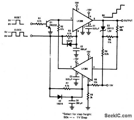
STAIRCASE_GENERATOR
Published:2009/6/26 3:01:00 Author:Jessie
View full Circuit Diagram | Comments | Reading(0)
LOGARITHMIC_WATTMETER
Published:2009/6/26 2:59:00 Author:Jessie
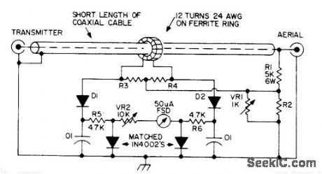
Single meter scale covers 1-1000W, with equally spaced divisions for 1,10,100,and 1000. This log scale makes it possible to measure very low reflected powers and very high forward powers simultaneously with same percentage accuracy.
Basis of operation is that voltage dropped across forward-biased 1N40C2 silicon PN junction diode is proportional to logarithm of cur rent through it. For 50-ohm line, use 220 for R2 and 27 for R3 and R4. For 75 ohm Iine, coffesponding values are 180 and 33. Detectordiodes are point-contact germanium rated at 80 PIV.
Article gives construction details. Ground coax braid at one end only. Ferrite ring is 0.5-inch Mullard FX1596 or equivalent.-P.G.Martin, Some Directional Wattmeters and a Novel SWR Meter, 73Magazine,Aug.1974,p 17,19-21,23-24,and 26. (View)
View full Circuit Diagram | Comments | Reading(3539)
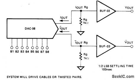
HIGH_SPEED_VOLTAGE_OUTPUT_DAC
Published:2009/6/26 2:57:00 Author:Jessie

View full Circuit Diagram | Comments | Reading(1703)
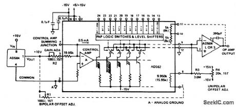
±10_V_FULL_SCALE_UNIPOLAR_DAC
Published:2009/6/26 2:51:00 Author:Jessie
View full Circuit Diagram | Comments | Reading(1682)
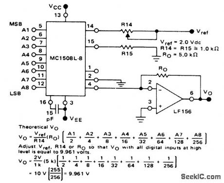
16_BIT_BINARY_DAC
Published:2009/6/26 2:43:00 Author:Jessie
View full Circuit Diagram | Comments | Reading(1654)
8_BIT_D_A_WITH_OUTPUT_CURRENT_TO_VOLTAGE_CONVERSION
Published:2009/6/26 2:40:00 Author:Jessie
View full Circuit Diagram | Comments | Reading(1621)
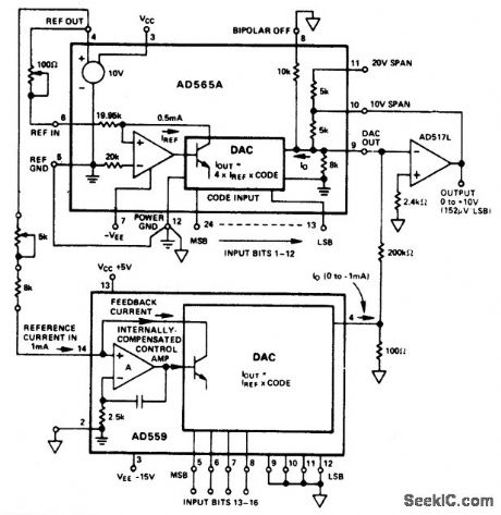
±10_V_FULL_SCALE_BIPOLAR_DAC
Published:2009/6/26 2:37:00 Author:Jessie
View full Circuit Diagram | Comments | Reading(1380)
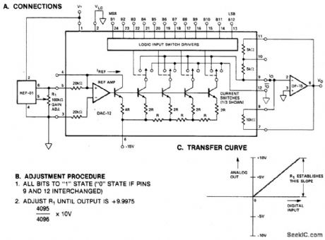
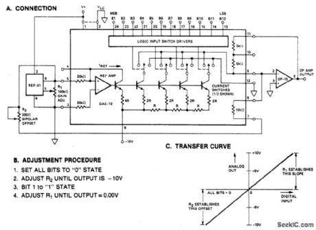
PRECISION_12_BIT_D_A_CONVERTER
Published:2009/6/26 2:35:00 Author:Jessie

View full Circuit Diagram | Comments | Reading(2369)
NOISE_BRIDGE
Published:2009/6/26 2:31:00 Author:Jessie


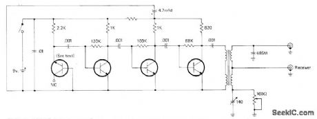
Used with communication receiver to measure impedance at antenna terminals or at end of transmission line, as required for adjusting antenna matching and loading devices for desired impedance at specific frequency. Consists of diode.connected transistor broadband,noise generator, 3-stage noise amplifier, and toroid transformer bridge.
All transistors are 2N5129 or equivalent 2N5137 or 2N5220. Try different transistors until highest noise output is obtained. Toroid core for trans.former is 3/8-inch Indiana General CF102. Quadrifilar winding has 4 1/2 turns of four No.28 enamel wires twisted together, wound on core and connected as on diagram. Noise bridge can also serve as wideband noise source for signal injection during troubleshooting in AF or RF circults, and as noise source for aligning RF cir-cuits,-J.J. Schultz, An Improved Antenna Noise Bridge, CQ, Sept, 1976, p 27-29 and 75. (View)
View full Circuit Diagram | Comments | Reading(3352)
LOGARITHMIC_WATTMETER
Published:2009/6/26 2:59:00 Author:May
Single meter scale covers 1-1000W, with equally spaced divisions for 1,10,100,and 1000. This log scale makes it possible to measure very low reflected powers and very high forward powers simultaneously with same percentage accuracy.
Basis of operation is that voltage dropped across forward-biased 1N40C2 silicon PN junction diode is proportional to logarithm of cur rent through it. For 50-ohm line, use 220 for R2 and 27 for R3 and R4. For 75 ohm Iine, coffesponding values are 180 and 33. Detectordiodes are point-contact germanium rated at 80 PIV.
Article gives construction details. Ground coax braid at one end only. Ferrite ring is 0.5-inch Mullard FX1596 or equivalent.-P.G.Martin, Some Directional Wattmeters and a Novel SWR Meter, 73Magazine,Aug.1974,p 17,19-21,23-24,and 26. (View)
View full Circuit Diagram | Comments | Reading(0)
HIGH_SPEED_VOLTAGE_OUTPUT_DAC
Published:2009/6/26 2:57:00 Author:May
View full Circuit Diagram | Comments | Reading(0)
±10_V_FULL_SCALE_UNIPOLAR_DAC
Published:2009/6/26 2:51:00 Author:May
View full Circuit Diagram | Comments | Reading(0)
16_BIT_BINARY_DAC
Published:2009/6/26 2:43:00 Author:May
View full Circuit Diagram | Comments | Reading(0)
8_BIT_D_A_WITH_OUTPUT_CURRENT_TO_VOLTAGE_CONVERSION
Published:2009/6/26 2:40:00 Author:May
View full Circuit Diagram | Comments | Reading(0)
±10_V_FULL_SCALE_BIPOLAR_DAC
Published:2009/6/26 2:37:00 Author:May
View full Circuit Diagram | Comments | Reading(0)
PRECISION_12_BIT_D_A_CONVERTER
Published:2009/6/26 2:35:00 Author:May
View full Circuit Diagram | Comments | Reading(0)
NOISE_BRIDGE
Published:2009/6/26 2:31:00 Author:May
Used with communication receiver to measure impedance at antenna terminals or at end of transmission line, as required for adjusting antenna matching and loading devices for desired impedance at specific frequency. Consists of diode.connected transistor broadband,noise generator, 3-stage noise amplifier, and toroid transformer bridge.
All transistors are 2N5129 or equivalent 2N5137 or 2N5220. Try different transistors until highest noise output is obtained. Toroid core for trans.former is 3/8-inch Indiana General CF102. Quadrifilar winding has 4 1/2 turns of four No.28 enamel wires twisted together, wound on core and connected as on diagram. Noise bridge can also serve as wideband noise source for signal injection during troubleshooting in AF or RF circults, and as noise source for aligning RF cir-cuits,-J.J. Schultz, An Improved Antenna Noise Bridge, CQ, Sept, 1976, p 27-29 and 75. (View)
View full Circuit Diagram | Comments | Reading(0)
CAPACITIVE_ANTENNA
Published:2009/6/26 2:31:00 Author:May
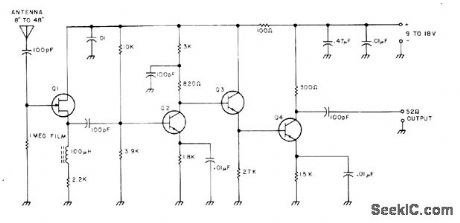
Cornbination of short whip antenna and broadband amplifier gives antenna covering entire range of 3 to 30 MHz without frequency selectivity. at is 2N3819 FET source follower driving three-transistor amplifier using 2N918, 2N6008, or other 200-MHz 20V NPN transistors to provide 30-dB gain. Circuit rolloff starts at 3 and 35 MHz. High gain of am plifier makes combination simulate quarter-wave whip over entire frequency range.-R. C.Wilson, The Incredible 18 All-Band Antenna, 73 Magazine, March 1975, p 49-50. (View)
View full Circuit Diagram | Comments | Reading(3148)
160_METER_PREAMP_WITH_FERRITE_LOOP
Published:2009/6/26 2:30:00 Author:May
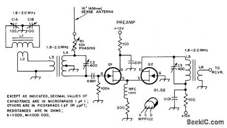
Ferrite-rod antenna is combined with 16-inch wire rod to give cardioid radiation pattern for low-noise 160-meter antenna system. Preamp using MPF102 FETs has gain of 25 dB. L1 is 48 turns No.14 enamel spread to 4.5 inches on 0.5 inch Amidon ferrite rod 7 inches long. L2 is 6-turn link wound over center of L1.L4 and L5 are each 50 turns No.26 enamel on 780-2 powdered-iron toroid cores, with 6 turns for links L3 and L6.-D. DeMaw, Low-Noise Receiving An-tennas, QST, Dee.1977, p 36-39. (View)
View full Circuit Diagram | Comments | Reading(3673)
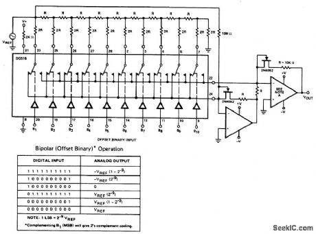
10_BIT,4_QUADRANT_MULTIPLEXING_D_A_CONVERTER(OFFSET_BINARY_CODING)
Published:2009/6/26 2:29:00 Author:May
View full Circuit Diagram | Comments | Reading(964)
| Pages:1286/2234 At 2012811282128312841285128612871288128912901291129212931294129512961297129812991300Under 20 |
Circuit Categories
power supply circuit
Amplifier Circuit
Basic Circuit
LED and Light Circuit
Sensor Circuit
Signal Processing
Electrical Equipment Circuit
Control Circuit
Remote Control Circuit
A/D-D/A Converter Circuit
Audio Circuit
Measuring and Test Circuit
Communication Circuit
Computer-Related Circuit
555 Circuit
Automotive Circuit
Repairing Circuit