
Circuit Diagram
Index 1280
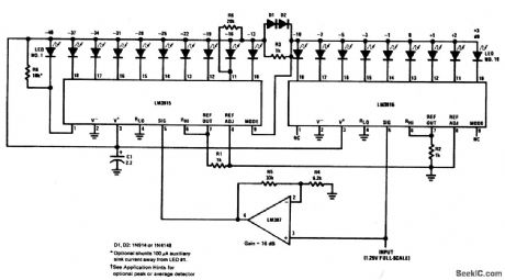
EXTENDED_RANGE_VU_METER(DOT_MODE)
Published:2009/6/28 21:05:00 Author:May
View full Circuit Diagram | Comments | Reading(0)
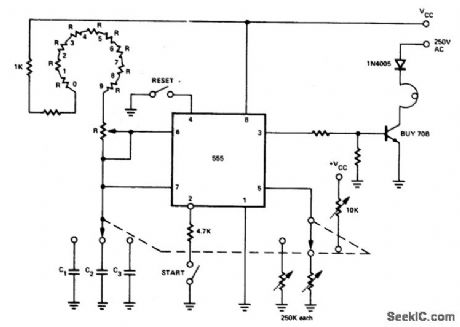
PHOTOGRAPHIC_TIMER
Published:2009/6/28 21:04:00 Author:May
View full Circuit Diagram | Comments | Reading(0)
SHUTTER_TESTER
Published:2009/6/28 21:03:00 Author:May
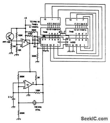
Shutter speed tester combines frequency counter, crystal oscillator, and photo-transistor-operated gate generator. Oscillator pulses are counted as long as the shutter is open. Reset is automatic at the instant the shutter opens.
(View)
View full Circuit Diagram | Comments | Reading(0)
FLASH_EXPOSURE_METER
Published:2009/6/28 21:02:00 Author:May
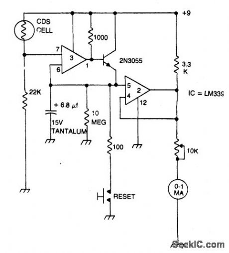
Strobe light meter catches the peak of flash intensity and holds it long enough to give a reading. The reset button must be pressed before each measurement. (View)
View full Circuit Diagram | Comments | Reading(0)
REMOTE_FLASH_TRIGGER
Published:2009/6/28 21:01:00 Author:May

Transistor Q1 is a light-activated silicon-controlled rectifier (LASCR). The gate is tripped by light entering a small lens built into the top cap. To operate, provide a 6-in. length of stiff wire for the anode and cathode connections and terminate the wires in a polarized power plug that matches the sync terminals on your electronic flashgun (strobelight). Make certain the anode lead connects to the positive sync terminal. When using the device, bend the connecting wires so the LASCR lens faces the main flash. This will fire the remote unit. (View)
View full Circuit Diagram | Comments | Reading(0)
FLASH_SLAVE_DRIVER
Published:2009/6/28 20:58:00 Author:May
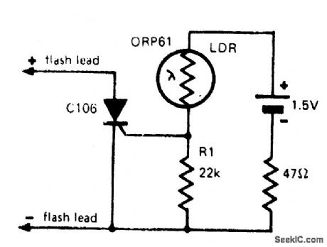
In photography, a separate flash, triggered by the light of a master flash light, is often required to provide more light, fill-in shadows etc. The sensitivity of this circuit depends on the proximity of the master flash and the value of R1. Increasing R1 gives increased sensitivity. (View)
View full Circuit Diagram | Comments | Reading(1434)
SOUND_ACTIVATED_STROBE_TRIP
Published:2009/6/28 20:57:00 Author:May
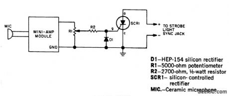
Take strobe-flash pictures the instant a pin pricks a balloon, a hammer breaks a lamp bulb or a bullet leaves a gun. Use a transistor amplifier of 1-watt rating or less. (It must have an output transformer.) The amplifier is terminated with a resistor on its highest output impedance, preferably 16 ohms. To test, darken room lights, open camera shutter, and break a lamp bulb with a hammer. The sound of the hammer striking the lamp will trigger the flash, and the picture will have been taken at that instant. (View)
View full Circuit Diagram | Comments | Reading(0)
SOUND_LIGHT_FLASH_TRIGGER
Published:2009/6/28 20:55:00 Author:May
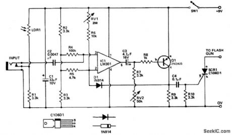
Sound input to the microphone triggers tthe IC monostable circuit which subsequently triggers an SCR, and hence the flash, after a time delay. This delay is adjustable—by varying the monostable on-time—from from 5 milliseconds to 200 milliseconds. (View)
View full Circuit Diagram | Comments | Reading(0)
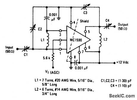
60_MHz_POWER_GAIN_TEST_CIRCUIT
Published:2009/6/28 21:09:00 Author:Jessie
View full Circuit Diagram | Comments | Reading(1157)
PHOTO_STOP_ACTION
Published:2009/6/28 20:52:00 Author:May
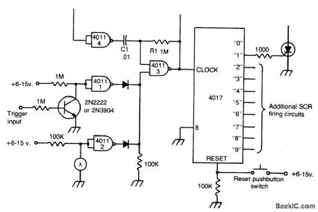
This circuit gives multiple stop-action photographic effects like showing a bouncing ball in up to nine locations in a single photograph. The circuit will automatically fire the bulbs sequentially with the time between each firing variable. The circuit is functionally complete except for the actual firing system. In many cases, a simple SCR will work, as shown. The firing can be initiated in one of two ways. A trigger pulse can be applied to the trigger input terminal through a capacitor, or can operate the unit as a slave. Light from a camera-mounted flash will activate the circuit through its built-in photocell pickup. The time period between each successive flash is determined by C1 and R1, which is variable. Afterfiring the circuit, it must be reset by momentarily depressing the reset button. (View)
View full Circuit Diagram | Comments | Reading(1005)
POWER_METER(1_kW_FULL_SCALE)
Published:2009/6/28 21:09:00 Author:Jessie
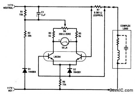
The circuit is intended for 117 Vac ±50 Vac operation, but can be easily modified for higher or lower voltages. It measures true (nonreactive) power be ing delivered to the load and requires no external power supply. Idling power drain is only 0.5 W. Load current sensing voltage is only 10 mV, keeping load voltage loss to 0.01%. Rejection of reactive load currents is better than 100:1 for linear loads. Nonlinearity is about 1% full scale when using a 50 μA meter movement. (View)
View full Circuit Diagram | Comments | Reading(1287)
DARKROOM_TIMER
Published:2009/6/28 20:50:00 Author:May
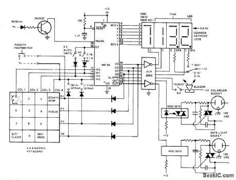
The darkroom timer/controller uses few external components: a display, a digit driver, keyboard, and output switching devices. A 4-digit common-cathode LED display is desirable for dark room environments. The time base is provided by shaping up the 50/60 Hz ac line. A DPDT switch (S1) is used to select a resolution of .1 or 1 seconds and to simultaneously move the decimal point. Timer/ controller has two switched ac outlets, one for the enlarger and one for the safe light. They are the complements of each other in that the safe light is on when the enlarger is not active and is off when the enlarger is printing. The buzzer is of the self-contained oscillator variety and operates with dc drive. (View)
View full Circuit Diagram | Comments | Reading(0)
AUTOMATIC_CONTRAST_METER
Published:2009/6/28 20:48:00 Author:May
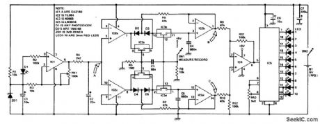
The circuit arrangement consists of a photo-amplifier which feeds a voltage derived from varying light levels in an enlarger to a pair of peak detectors. One follows the peak positive voltage and the other the peak negative voltage. The capacitors used for storing the voltage peaks in the followers also form part of sample and hold circuits which are then switched to hold after the measurement. Their outputs represent the maximum and minimum values of light intensity. A differential amplifier then computes the ratio of these values, and the result is displayed on an LED bargraph meter. (View)
View full Circuit Diagram | Comments | Reading(881)
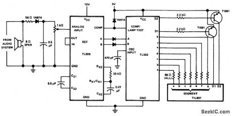
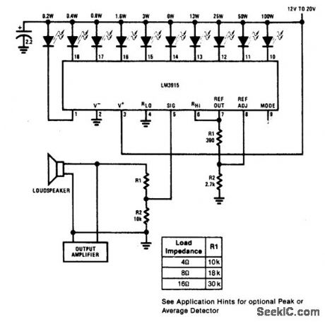
1AUDIO_POWER_METER
Published:2009/6/28 21:07:00 Author:Jessie
View full Circuit Diagram | Comments | Reading(1512)
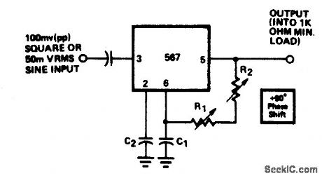
0°TO_360°PHASE_SHIFTER
Published:2009/6/28 20:45:00 Author:May
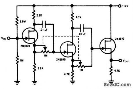
Each stage provides 0°to 180°phase shift. By ganging the two stages,0°to 360°phase shift is achieved.The 2N3070 JFETs do not load the phase shift networks. (View)
View full Circuit Diagram | Comments | Reading(891)
SOLID_STATE_AUTO_REGULATOR
Published:2009/6/28 21:06:00 Author:Jessie
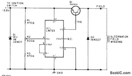
Replaces and outperforms electromechanical charging-voltage regulator in autos using altemator systems. Prolongs battery life by preventing un dercharging or overcharging of 12-V lead-acid battery. Uses LM723 connected as sia;itching regulatorfor controlling altematorfield cument. R2 is adjusted to maintain 13.8.V fully charged voltage for standard auto battery. Article gives construction details and tells how to use external relay to maintain altemator charge-indica-torfunction in cars having idiot light ratherthan charge-discharge ammeter. Q1 is 2N2063A (SK3009) 10-A PNP transistor.-W. J. Prudhomme, Build Your Own Car Regulator, 73 Magazine, March 1977, p 160-162. (View)
View full Circuit Diagram | Comments | Reading(4486)
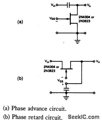
PHASE_SHIFT_CIRCUITS
Published:2009/6/28 20:43:00 Author:May
View full Circuit Diagram | Comments | Reading(827)
AUDIO_POWER_METER
Published:2009/6/28 21:06:00 Author:Jessie
View full Circuit Diagram | Comments | Reading(1548)
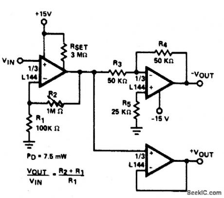
PRECISION_PHASE_SPLITTER
Published:2009/6/28 20:42:00 Author:May
View full Circuit Diagram | Comments | Reading(1)
0°TO_180°PHASE_SHIFTER
Published:2009/6/28 20:42:00 Author:May
View full Circuit Diagram | Comments | Reading(752)
| Pages:1280/2234 At 2012611262126312641265126612671268126912701271127212731274127512761277127812791280Under 20 |
Circuit Categories
power supply circuit
Amplifier Circuit
Basic Circuit
LED and Light Circuit
Sensor Circuit
Signal Processing
Electrical Equipment Circuit
Control Circuit
Remote Control Circuit
A/D-D/A Converter Circuit
Audio Circuit
Measuring and Test Circuit
Communication Circuit
Computer-Related Circuit
555 Circuit
Automotive Circuit
Repairing Circuit