
Circuit Diagram
Index 1263
AUTO_RADIO_AMPLIFIER
Published:2009/6/28 23:29:00 Author:May
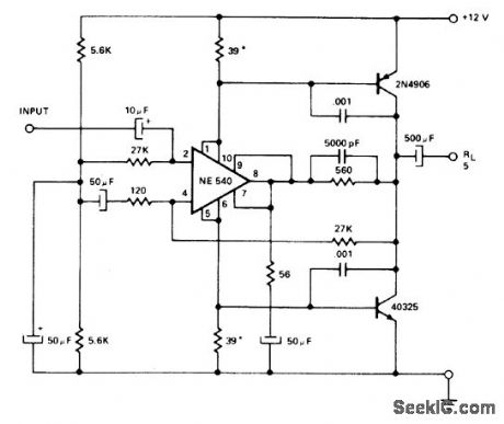
Circuit shown per-mits operation of Slgnetics NE540 power driver front single-polarity 12-V supply of auto. Bipolar supplies for differential inputs of 540 are achieved by returning inputs to half of available supply or 6 V. Load is AC coupled because am piif et has DC gain of 1, and amplifier output is therefore 6 VDC. 39-ohm supply resistors are selected for minimum crossover distortion.- Signetics Analog Data Manual, Signetics, Sunnyvale, CA, 1977, p 764. (View)
View full Circuit Diagram | Comments | Reading(1532)
74 Series digital circuit of 74365A/366A six buffer / bus driver(three-state)
Published:2011/8/1 1:22:00 Author:Lucas | Keyword: 74 Series , digital circuit , six buffer , bus driver, three-state
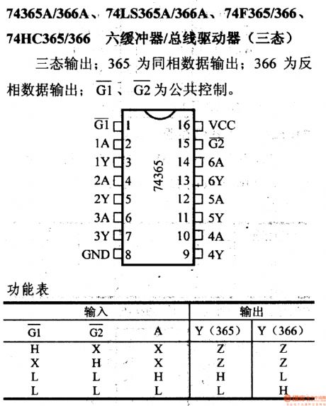
Three-state output; 365 is the in-phase output; 366 is the inverted output; G1 and G2 are the public control.
(View)
View full Circuit Diagram | Comments | Reading(748)
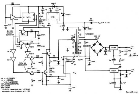
Ultra_lown_noise_5_to_±15_V_converter
Published:2009/7/25 1:59:00 Author:Jessie
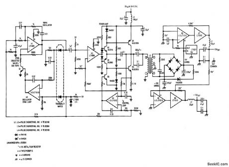
This circuit converts 5V to ±15V at 75mA,with an output noise of less than 30μV p-p(2ppm) (View)
View full Circuit Diagram | Comments | Reading(611)
WIPER_DELAY_CONTROL
Published:2009/6/28 23:27:00 Author:May
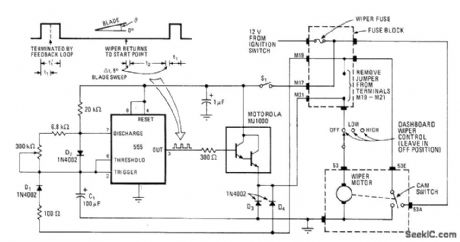
555 timer prvides selsctavel delay tiem between sweeps of wiper blades driven by motor in negative-ground system. Article also gives circuit modification for positive-ground autos. Delay time can ve varied between 0 and 22s. Timer uses feedback signal from cam-operated switch of motor to synchronize delay time with position of wiper blades.-J.Okolwicz, Synchronous Timing Loop Controls Windshield Wiper Delay, Electronics, Nov. 24, 1977, P 115 and 177. (View)
View full Circuit Diagram | Comments | Reading(2371)
Norton_fourth_order_250_kHz_bessel_filter
Published:2009/7/25 1:57:00 Author:Jessie
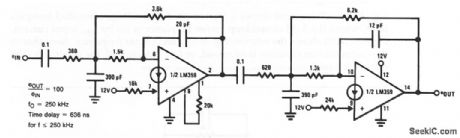
This circuit uses two sections of a Norton to form a Bessel filter. (View)
View full Circuit Diagram | Comments | Reading(1549)
The light detection single power source circuit
Published:2011/7/21 2:53:00 Author:Seven | Keyword: single power source
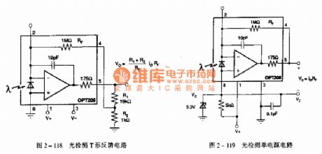
The light sensor OPT209 LED computing amplifier integrated circuit Functions: used in positioning and approaching sensors, fog detection, photo analysis and medical devices, etc.
(View)
View full Circuit Diagram | Comments | Reading(733)
74 Series digital circuit of 74367A/368A six buffer / bus driver
Published:2011/8/1 1:20:00 Author:Lucas | Keyword: 74 Series, digital circuit, six buffer , bus driver
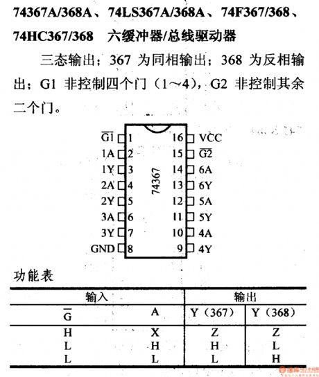
Three-state output; 367 is the in-phase output; 368 is the inverted output; G1 non-controls four doors (1 ~ 4), and G2 non-controls the other two doors.
(View)
View full Circuit Diagram | Comments | Reading(891)
Low_noise_5__to_±15_V_converter
Published:2009/7/25 1:57:00 Author:Jessie
This circuit converts 5 V to ±15 V at 250 mA, with an output noise of about 200 μV peak-to-peak. (View)
View full Circuit Diagram | Comments | Reading(1119)
The light detecion 4-20mA current transformer circuit
Published:2011/7/21 2:56:00 Author:Seven | Keyword: light detecion, current transformer
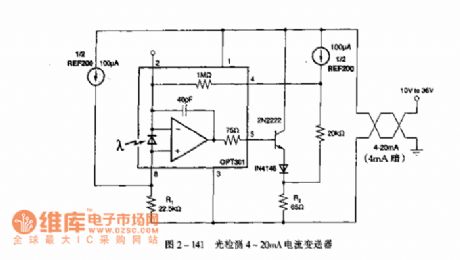
Figure 2-141. The light detecion 4-20mA current transformer circuit (View)
View full Circuit Diagram | Comments | Reading(1993)
LATCH_COMPARATORS_FORM_3_BIT_A_D_CON_VERTER
Published:2009/6/28 23:27:00 Author:May
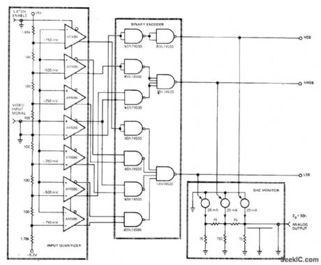
Seven Advanced Micro Devices AM686 comparators are arranged for direct parallel conversion of rapidly changing input signals, without prior sample-and-hold conditioning. Comparators feed Schottky TTL binary encoder logic for encoding to 3-bit offset binary. Quantization process is monitored by D/A converter. Article describes operation in detail and gives performance graphs which show freedom from output glitching at conversion speeds under 12 ns.—S.Dendinger,Try the Sampling Comparator in Your Next A/D Interface Design,EDN Magazine,Sept.20,1976,p 91—95. (View)
View full Circuit Diagram | Comments | Reading(1857)
Norton_high_gain_general_purpose_amplifier
Published:2009/7/25 1:55:00 Author:Jessie
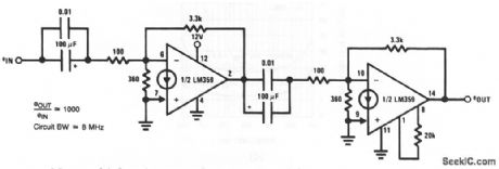
This circuit uses two sections of a Norton to form a general-purpose amplifier with voltage gains of 1000 over an 8-MHz bandwidth. (View)
View full Circuit Diagram | Comments | Reading(723)
Norton_high_yoerforrnance_video_amplifier
Published:2009/7/25 1:54:00 Author:Jessie
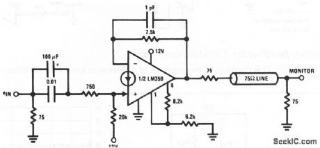
This circuit shows a Norton used as a noninverting video amplifier: Typical voltage gain is 20 dB, with a -3-dB bandwidth from 2.5 Hz to 25 MHz, and a 4-V pp output swing. Differential phase error is less than 1°, and differential gain error is less than 2% at 3.58 MHz. A typical signal source can be either detected video from a receiver or possibly from a camera signal. (View)
View full Circuit Diagram | Comments | Reading(785)
2_W_WITH_IC
Published:2009/6/28 23:26:00 Author:May

Uses Motorola MFC9020 audio power amplifier to give maximum output of about 2 W for 16-ohm loudspeaker. Used in autopatch system for FM repeaten-R. B. Shreve, A Versatile Autopatch System for VHF FM Repeaters, Ham Radio, July 1974, p 32-38. (View)
View full Circuit Diagram | Comments | Reading(1)
74 Series digital circuit of 74LS374 octal D flip-flop(tristate)
Published:2011/7/25 3:31:00 Author:Lucas | Keyword: 74 Series , digital circuit , octal D flip-flop, tristate
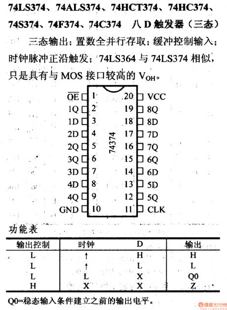
Three-state output: all the load is full parallel stored; it has buffer control input; clock pulse positive edge is triggered; 74LS364 is the similar to 74LS374 but has the MOS interface, high VOH.
Q0 = the output level before establishing the steady-state input conditions.
(View)
View full Circuit Diagram | Comments | Reading(2266)
Off_line_multiple_output_flyback_converter
Published:2009/7/25 1:54:00 Author:Jessie
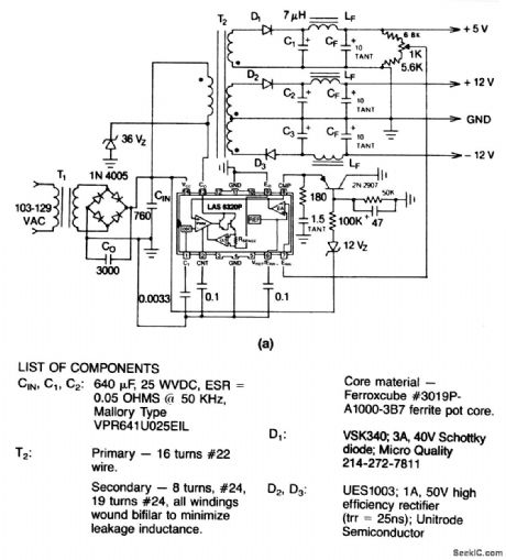
This circuit provides +5 V at 1 A, +12 V at 0.2 A, and -12 V at 0.2 A from a 103- to 129-Vac line input. Figure 4-38B shows component source information. (View)
View full Circuit Diagram | Comments | Reading(874)
Norfort_voltage_controlled_low_pass_filter
Published:2009/7/25 1:52:00 Author:Jessie
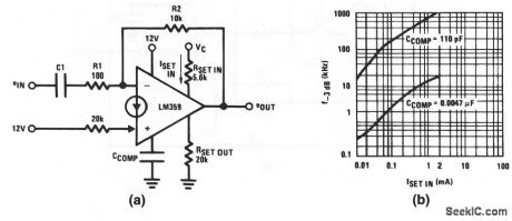
This circuit shows a Norton used as a voltage-controlled low-pass filter, where the 3-dB closed-loop corner frequency is set by ISET input current.Figure 11-16B shows the relationship of ISET and corner frequency. Note that as the compensation capacitor is increased, or ISET is decreased, the maximum slew ratd is decreased. (View)
View full Circuit Diagram | Comments | Reading(933)
LOW_COST_30_W
Published:2009/6/28 23:25:00 Author:May
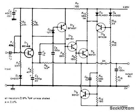
Economical compromise gives 30 W into 8-ohm load at 0.1% distortion (mainly second harmonic) and hum level of -50 dBW. Article covers design and operation of cir, cuit in detail.-P. L, Taylot, Audio Power Am-plifier, Wireless Wolld, June 1973, p 301-302, (View)
View full Circuit Diagram | Comments | Reading(649)
70_dB_GAIN_WITH_15_V
Published:2009/6/28 23:24:00 Author:May

Operates from sihgle penlight qell at current drain of 0.5 mA. ldeal as self-contained unit inserted in microphone cable. Q2-Q4 form 70-dB voltage amplifier. Q5 is detector, and Q6 is emitter-follower driving AGC transistor Q1.3-dB bandwidth is about 100 Hz to 8 kHz. Full output is about 200 mVRMS, while low output terminal is 1 mVRMS.-C.Hall, Low-Voltage Audio AGO Amplifier, Ham Radio, Dec. 1973, p 32-34. (View)
View full Circuit Diagram | Comments | Reading(3480)
74 Series digital circuit of 74LS385, 74F385 four serial adder / subtractor
Published:2011/8/1 1:15:00 Author:Lucas | Keyword: 74 Series , digital circuit , four serial adder , subtractor
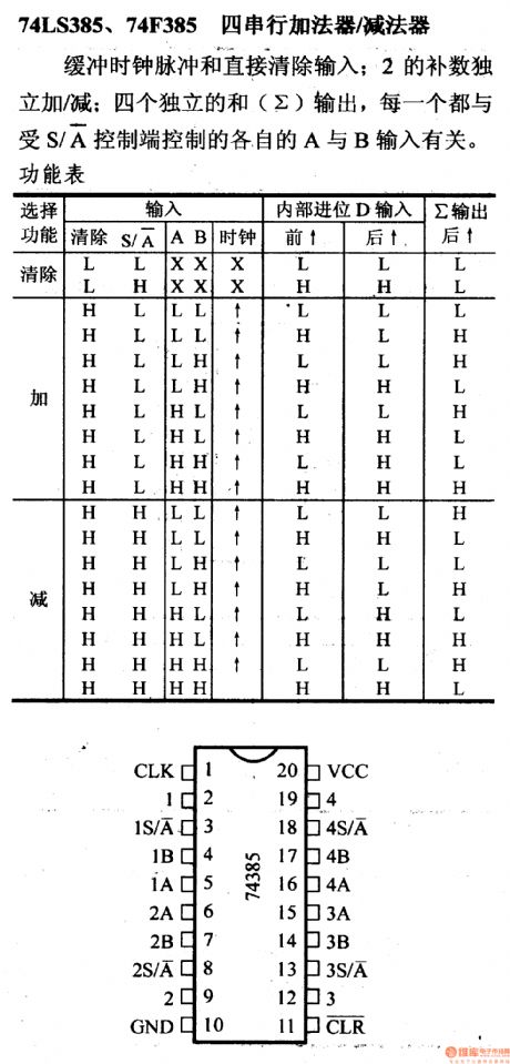
It has buffered clock and direct clear input; 2's complement independent add/ subtract and four independent outputs are related to A and B inputs controlled by S / A console.
(View)
View full Circuit Diagram | Comments | Reading(1492)
Flyback_converter
Published:2009/7/25 1:51:00 Author:Jessie
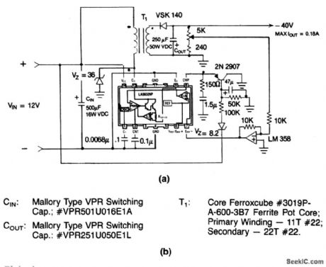
This circuit provides a -40-V output at 0.18 A from a +12-V input.Component source information is given in Fig. 4-37B. (View)
View full Circuit Diagram | Comments | Reading(775)
| Pages:1263/2234 At 2012611262126312641265126612671268126912701271127212731274127512761277127812791280Under 20 |
Circuit Categories
power supply circuit
Amplifier Circuit
Basic Circuit
LED and Light Circuit
Sensor Circuit
Signal Processing
Electrical Equipment Circuit
Control Circuit
Remote Control Circuit
A/D-D/A Converter Circuit
Audio Circuit
Measuring and Test Circuit
Communication Circuit
Computer-Related Circuit
555 Circuit
Automotive Circuit
Repairing Circuit