
Circuit Diagram
Index 1279
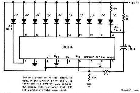
BAR_DISPLAY_WITH_ALARM_FLASHER
Published:2009/6/28 21:21:00 Author:May
View full Circuit Diagram | Comments | Reading(978)
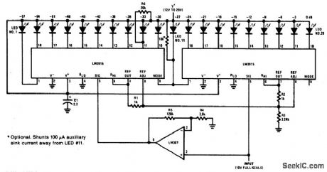
60_dB_DOT_MODE_DISPLAY
Published:2009/6/28 21:20:00 Author:May
View full Circuit Diagram | Comments | Reading(878)
SINGLE_ENDED_REGULATOR
Published:2009/6/28 21:20:00 Author:May
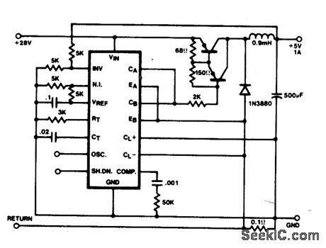
In this conventional single-ended regulator circuit,the two outputs of the SG1524 are connected in parallel for effective 0-90%duty-cycle modulation. The use of an output inductor requlres an RC phase compensation network for loop stability. (View)
View full Circuit Diagram | Comments | Reading(890)
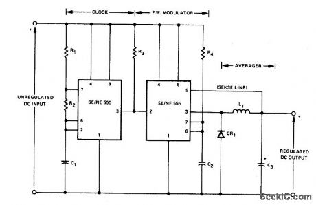
SWITCHING_STEP_DOWN_REGULATOR
Published:2009/6/28 21:18:00 Author:May
View full Circuit Diagram | Comments | Reading(749)
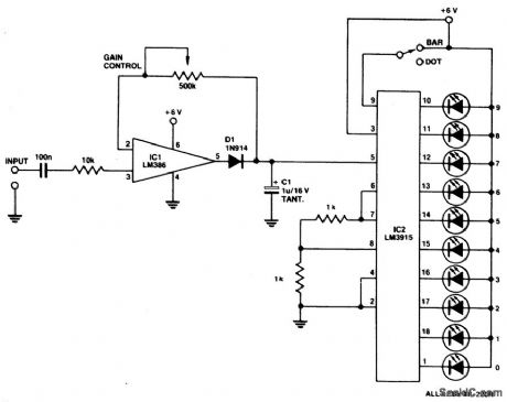
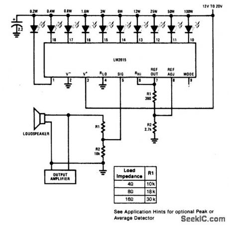
LED_BAR_DOT_LEVEL_METER
Published:2009/6/28 21:18:00 Author:May
Circuit Notes
A simple level of power meter can be arranged to give a bar or dot display for a hi-fi system. Use green LEDs for 0 to 7; yellow for 8 and red for 9 to indicate peak power. The gain control is provided to enable alibration on the equipment with which the unit is used. Because the unit draws some 200 mA, a power supply is advisable instead of running the unit from bat-teries. (View)
View full Circuit Diagram | Comments | Reading(1666)
REGULATED_SPLIT_POWER_SUPPLIES_FROM_A_SINGLE_SUPPLY
Published:2009/6/28 21:17:00 Author:May
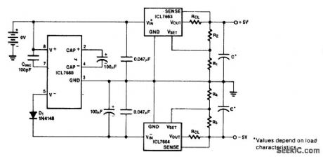
The oscillation frequency of the ICL7660 is reduced by the external oscillator capacitor, so that it inverts the battery voltage more efficiently. (View)
View full Circuit Diagram | Comments | Reading(1224)
SPEED_TRAP
Published:2009/6/28 21:17:00 Author:May
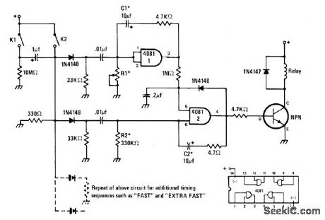
Time required for auto to activate sensors placed measured distance apart on driveway or road is used to energize relay or alarm circuit when auto exceeds predetermined speed. If speed limit chosen is 15 mph, set detectors 22 feet apart for travel time of 1 s. Sensors can be photocells or air-actuated solenoids. For most applications, R1 can be 1-megohm pot. Transistor type is not critical. Values of R2 and C2 determine how long alarm sounds.-J. Sandier, 9 Projects under $9, Modem Electronics, Sept. 1978, p 35-39. (View)
View full Circuit Diagram | Comments | Reading(1688)
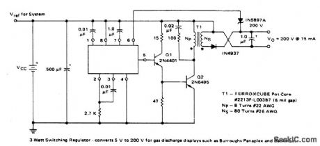
3_W_SWITCHING_REGULATOR_APPLICATION_CIRCUIT
Published:2009/6/28 21:16:00 Author:May
View full Circuit Diagram | Comments | Reading(675)
5_V,05_A_POWER_SUPPLY
Published:2009/6/28 21:15:00 Author:May
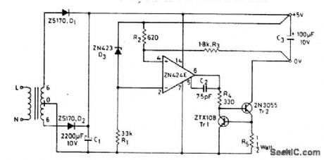
The circuit is essentially a constant source modified by the feedback components R2 and R3 to give a constant voltage output.The output of the ZN424E need only be 2 volts above the negative rail, by placing the load in the collector of the output transistor Tr1. The current circuit is achieved by Tr1 and R5. This simple circuit has the following performance characteristics: Output noise and ripple (full load) = 1 mV rms. Load regulation (0 to 0.5 A) = 0.1%. Temperature coefficient = ± 100 ppm/℃. Current limit = 0.65 A. (View)
View full Circuit Diagram | Comments | Reading(720)
LED_BRIGHTNESS_CONTROL
Published:2009/6/28 21:14:00 Author:May
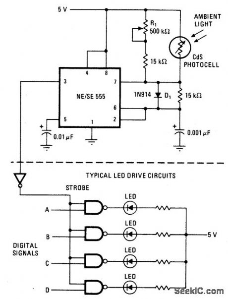
Circuit NotesThe brightness of LED display is varied timing resistor to boost the timer's maximum by using a photocell in place of one timing duty cycle. The result is a brighter display in resistor in a 555 timer, and bypassing the other sunlight and a fainter one in the dark. (View)
View full Circuit Diagram | Comments | Reading(877)
105_GHz_RADAR_DETECTOR
Published:2009/6/28 21:13:00 Author:May
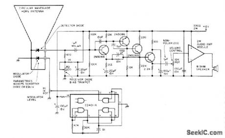
Picks up CW Doppler traffic radar signals in X-band region at 10.525 GHz and alerts speeding driver with audio tone. Article also tells how traffic radars work. By adding 10.5-6Hz oscillator, same cir-cuit can be used in 10.5.GHz amateur radio band for communicating with other cars using this band. Dimensioned diagram of horn is given.-S. M. Olberg, Mobile Smokey Detector, 73 Mag-azine, Holiday issue 1976, p 32-35. (View)
View full Circuit Diagram | Comments | Reading(5267)
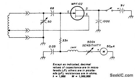
DIP_METER_USING_SILICON_JUNCTION_FET
Published:2009/6/28 21:13:00 Author:May
View full Circuit Diagram | Comments | Reading(1013)
SWITCHING_REGULATOR_OPERATING_AT_200_kHz
Published:2009/6/28 21:12:00 Author:May
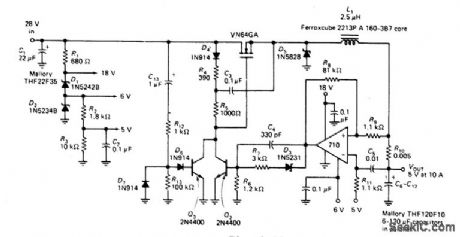
This circuit provides a regulated dc with less than 100 mV of ripple for microprocessor applications. Necessary operating voltages are taken from the bleeder resistor network connected across the unregulated 28 V supply. The output of the LM710 comparator (actually an oscillator running at 200 kHz) is fed through a level-shifting circuit to the base ofbipolar transistor Q2. This transistor is part of a bootstrap circuit necessary to turn the power MOSFET full on in totem-pole MOSFET arrays. (View)
View full Circuit Diagram | Comments | Reading(1566)
GATE_DIP_METER_COVERS_18_150_MHz
Published:2009/6/28 21:11:00 Author:May
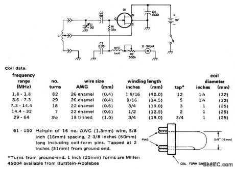
View full Circuit Diagram | Comments | Reading(911)
MILEAGE_COMPUTER
Published:2009/6/28 21:10:00 Author:May
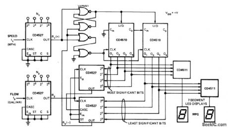
Fuel consumption in miles per gallon is continuously updated on 2-dight LED display. Entire system using CMOS ICs can be built for Iess than $25 including as-flow sensor and speed sensor, sources for which are given in article along with operational details. Circuit uses rate multiplier to produce output pulse train whose frequency is proportional to product of the two inputs. Output rate is time-averaged. Speed sensor, mounted in series with speedometer cable, feeds speed data to CD4527 rate multiplier as clock input. Gas-flow sensor, mounted in series with fuel line, feeds clock input of other rate multiplier.-G. J. Summers, Miles/Gallon Measurement Made Easy with CMOS Rate Multipliers, EDN Magazine, Jan. 20, 1976,p 61-63. (View)
View full Circuit Diagram | Comments | Reading(3035)
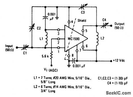
60_MHz_POWER_GAIN_TEST_CIRCUIT
Published:2009/6/28 21:09:00 Author:May
View full Circuit Diagram | Comments | Reading(0)
POWER_METER(1_kW_FULL_SCALE)
Published:2009/6/28 21:09:00 Author:May
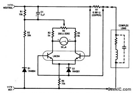
The circuit is intended for 117 Vac ±50 Vac operation, but can be easily modified for higher or lower voltages. It measures true (nonreactive) power be ing delivered to the load and requires no external power supply. Idling power drain is only 0.5 W. Load current sensing voltage is only 10 mV, keeping load voltage loss to 0.01%. Rejection of reactive load currents is better than 100:1 for linear loads. Nonlinearity is about 1% full scale when using a 50 μA meter movement. (View)
View full Circuit Diagram | Comments | Reading(0)
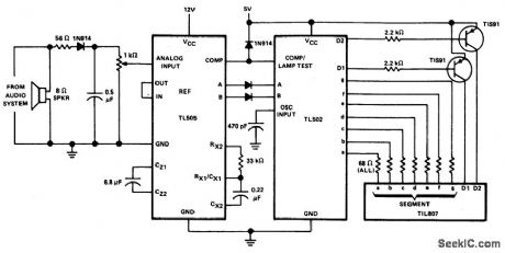
1AUDIO_POWER_METER
Published:2009/6/28 21:07:00 Author:May
View full Circuit Diagram | Comments | Reading(0)
SOLID_STATE_AUTO_REGULATOR
Published:2009/6/28 21:06:00 Author:May
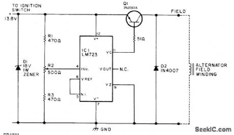
Replaces and outperforms electromechanical charging-voltage regulator in autos using altemator systems. Prolongs battery life by preventing un dercharging or overcharging of 12-V lead-acid battery. Uses LM723 connected as sia;itching regulatorfor controlling altematorfield cument. R2 is adjusted to maintain 13.8.V fully charged voltage for standard auto battery. Article gives construction details and tells how to use external relay to maintain altemator charge-indica-torfunction in cars having idiot light ratherthan charge-discharge ammeter. Q1 is 2N2063A (SK3009) 10-A PNP transistor.-W. J. Prudhomme, Build Your Own Car Regulator, 73 Magazine, March 1977, p 160-162. (View)
View full Circuit Diagram | Comments | Reading(0)
AUDIO_POWER_METER
Published:2009/6/28 21:06:00 Author:May
View full Circuit Diagram | Comments | Reading(0)
| Pages:1279/2234 At 2012611262126312641265126612671268126912701271127212731274127512761277127812791280Under 20 |
Circuit Categories
power supply circuit
Amplifier Circuit
Basic Circuit
LED and Light Circuit
Sensor Circuit
Signal Processing
Electrical Equipment Circuit
Control Circuit
Remote Control Circuit
A/D-D/A Converter Circuit
Audio Circuit
Measuring and Test Circuit
Communication Circuit
Computer-Related Circuit
555 Circuit
Automotive Circuit
Repairing Circuit