
Circuit Diagram
Index 1265
Switched_capacitor_5_V_to±12_V_converter
Published:2009/7/25 2:39:00 Author:Jessie
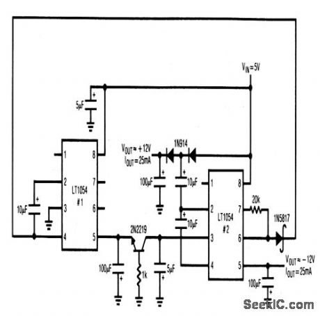
This circuit provides ±12-V outputs at 25 mA from a 5-V input. (View)
View full Circuit Diagram | Comments | Reading(615)
Switched_capacitor_voltage_boost_converter
Published:2009/7/25 2:38:00 Author:Jessie
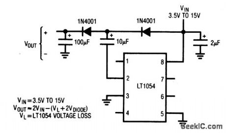
This circuit boosts the input voltage (to almost double),using two diodes and the LT1054. (View)
View full Circuit Diagram | Comments | Reading(927)
COMPLEMENTARY_SYMMETRY_AMPLIFIER
Published:2009/6/28 23:13:00 Author:May
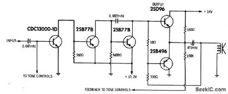
Simplified version of cicuit takes advantage of fact that PNP and NPN transistors require signais of opposite polatity to perform same function. Bases of output transistors are fed in parallel, with loudspeaker connected to common terminal of transistors. Drawback is difficulty of locating matched PNP and NPN transistors,-J. J. Carr, Solid-State Audio: A neview of the Latest Circuitry and General Troubleshooting Procedures, Electronic Servicing, Aug. 1971, p 38-43. (View)
View full Circuit Diagram | Comments | Reading(1274)
Switched_capacitor_6__to_±5_V_converter_
Published:2009/7/25 2:37:00 Author:Jessie
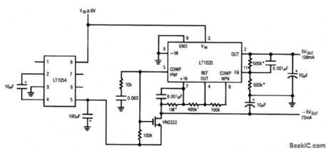
This circuit provides a +5-V output at 100mA and -5-V output at 75mA from a 6-V input. (View)
View full Circuit Diagram | Comments | Reading(625)
500_OHM_INPUT
Published:2009/6/28 23:12:00 Author:May
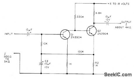
Simple audio amplifier having high gain, low noise, and excellent temperature stability can be used as mike booster, first AF amplifier stage in receiver, or for other preamp applications. With values shown, circult will amplify down to about 10 Hz. To increase low-frequency cutoff for speech amplifier, reduce 02 to 1μF or less.-E. Dusina, Build a General Purpose Preamp, 73 Magazine, Nov.1977,p 98. (View)
View full Circuit Diagram | Comments | Reading(1084)
Basic_switched_capacitor_converter_
Published:2009/7/25 2:36:00 Author:Jessie
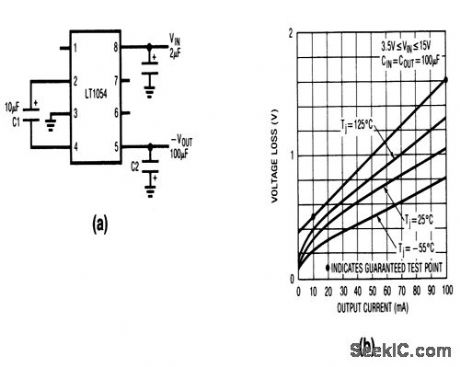
This circuit shows how a switched-capacitor building-block LT1054 can be used to convert positive input voltage to negative output voltage, with losses as shown in Fig.4-56B. (View)
View full Circuit Diagram | Comments | Reading(848)
15__to_10_V_Converter_with_20000_V_isolation
Published:2009/7/25 2:35:00 Author:Jessie
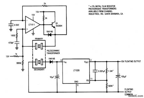
This circuit uses a piezoceramic transformer to isolate the output from the inputs. Common-mode voltages of 20,000 V are acceptable. (View)
View full Circuit Diagram | Comments | Reading(707)
Isolated_15__to_1000_V_converter
Published:2009/7/25 2:33:00 Author:Jessie
This circuit provides the same function as that of Fig. 4-53, except that the output is isolated (floating). Common-mode voltages of 2000 V are accept-able. (View)
View full Circuit Diagram | Comments | Reading(721)
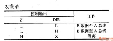
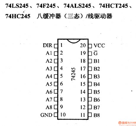
74 Series digital circuit of 74LS245,74F245 eight inverting buffer(three-state)/line driver
Published:2011/8/1 1:10:00 Author:Lucas | Keyword: 74 Series, digital circuit , eight inverting buffer, three-state), line driver
View full Circuit Diagram | Comments | Reading(4521)
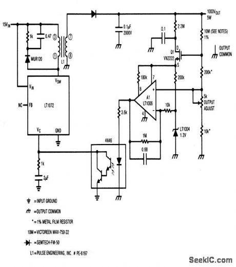
Nonisolated_15__to_1000_V_converter
Published:2009/7/25 2:32:00 Author:Jessie
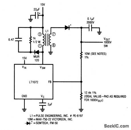
This circuit is suitable for use with photomultiplier tubes, ion generators, gas-based detectors, image intensifiers, or any application where the supply does not need to be isolated from the load. (View)
View full Circuit Diagram | Comments | Reading(713)
Linear_regulator_with_switching_pre_regulator
Published:2009/7/25 2:30:00 Author:Jessie
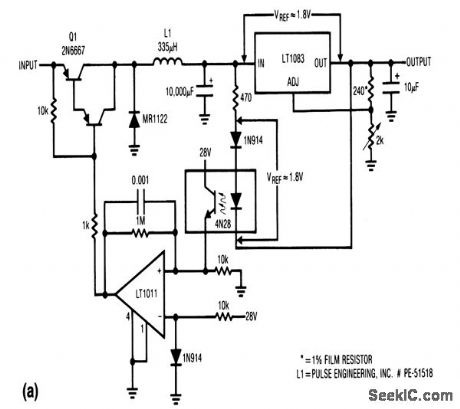
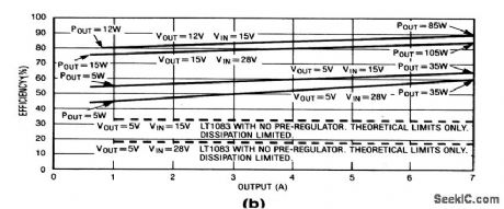
This circuit provides linear regulation (chapter 7), but with switching pre-regulation. The combination permits good efficiency with a wide range of input and output voltages, as shown in Fig. 4-52B (efficiency versus output current). (View)
View full Circuit Diagram | Comments | Reading(2153)
Positive_buck_boost_converter
Published:2009/7/25 2:28:00 Author:Jessie
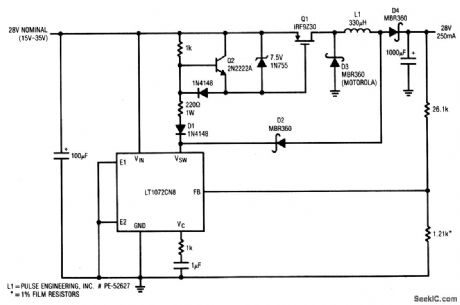
This circuit provides 28-V output at 250 mA for inputs from 15 to 35 V. (View)
View full Circuit Diagram | Comments | Reading(1196)
Positive_buck_converter_with_wide_input_range
Published:2009/7/25 2:25:00 Author:Jessie
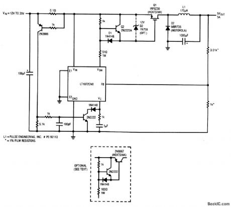
This circuit provides 5-V output at 5 A, for inputs from 12 to 35 V. If the PMOS transistor is replaced with a Darlington pnp transistor (shown in dashed lines), efficiency decreases. (View)
View full Circuit Diagram | Comments | Reading(988)
Positive_to_negative_flyback_converter_with_wide_mput_range
Published:2009/7/25 2:22:00 Author:Jessie
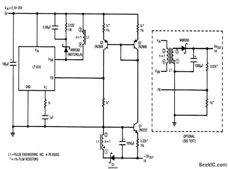
his circuit provides -5-V output at 1 A, for inputs from +3.5 to +35 V. Q1 introduces a -2 mV/℃ drift. This drtft can be compensated by the circuit showrn in dashed lines,although line regulation is somewhat degraded. (View)
View full Circuit Diagram | Comments | Reading(760)
74 Series digital circuit of 74290,74LS290 decimal counter
Published:2011/7/29 1:38:00 Author:Lucas | Keyword: 74 Series , digital circuit , decimal counter
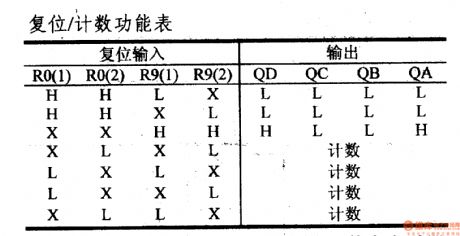
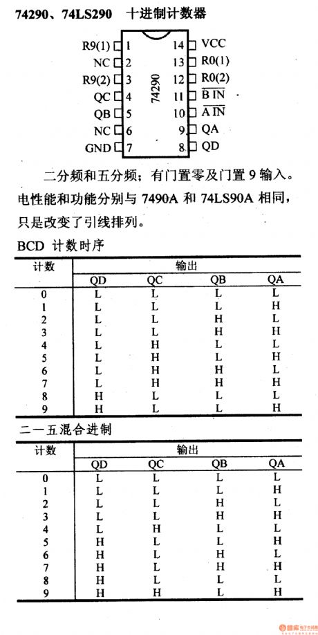
Frequency-halving and one-fifth frequency; it has zero gate and 9 inputs. Electrical performance and functionality are the same with the 7490A and 74LS90A. It just changes the lead arrangement.
(View)
View full Circuit Diagram | Comments | Reading(1845)
Extending_three_terminal_regulator_current_capability_with_shutdown
Published:2009/7/25 2:20:00 Author:Jessie
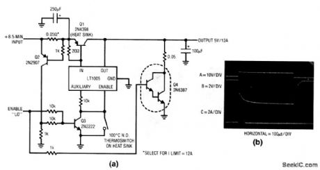
This circuit extends the 1-A capacity of an LT1005 multifunction regulator to 12 A, while retaining the enable feature and auxiliary 5-V output. Q2 senses the current-dependent voltage across the 0.05-Ω shunt (the shunt value can be selected for the desired current limit). When the shunt voltage reaches the desired shutoff point, Q2 turns on, biases Q3, and shuts down the regulator through the enable pin. The 100℃ thermoswitch limits dissipation in Q1 during prolonged short-circuit conditions by disabling the LT1005, and it should be mounted on the Q1 heatsink. Q4 can be omitted if fast turn-off is not needed. When the enable command is given (trace A, Fig. 9-8B) Q3 turns on, cuts off the LT1005, and forces Q1 off. Simultaneously, Q4 (if used) turns on and pulls down the regulator output (trace B). This sinks the 100-μF capacitor discharge current (trace C). (View)
View full Circuit Diagram | Comments | Reading(697)
Converter_with_wide_input_range
Published:2009/7/25 2:19:00 Author:Jessie
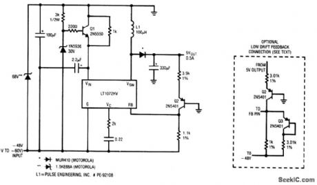
This circuit provides 5-V output at 0.5 A, for inputs from -40 V to -60 V. Q2 introduces a -2 mV/℃ drift. This drift can be compensated by the circuit shown in dashed lines,Jthough line regulation is somewhat degraded. (View)
View full Circuit Diagram | Comments | Reading(834)
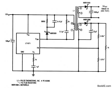
High_efficiency_converter_with_nonisolated_output
Published:2009/7/25 2:17:00 Author:Jessie
This circuit is a nonisolated version of the circuit in Fig. 4-46. (View)
View full Circuit Diagram | Comments | Reading(764)
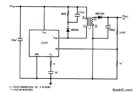
High_efficiency_converter_with_floating_output
Published:2009/7/25 2:16:00 Author:Jessie
This circuit provides 5-V output at 1 A for a 12-V input.Regulation stays within ±100 mV from 100% to 100% of output rating, with excursion exceeding 900 mV at no load.Notice that the outputis fully isolated. (View)
View full Circuit Diagram | Comments | Reading(798)
High_efficiency_buck_converter
Published:2009/7/25 2:14:00 Author:Jessie
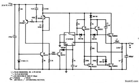
This circuit provides 5-V output at 5 A from a 9.5- to 14.5-V input, with about 90% efficiency. (View)
View full Circuit Diagram | Comments | Reading(912)
| Pages:1265/2234 At 2012611262126312641265126612671268126912701271127212731274127512761277127812791280Under 20 |
Circuit Categories
power supply circuit
Amplifier Circuit
Basic Circuit
LED and Light Circuit
Sensor Circuit
Signal Processing
Electrical Equipment Circuit
Control Circuit
Remote Control Circuit
A/D-D/A Converter Circuit
Audio Circuit
Measuring and Test Circuit
Communication Circuit
Computer-Related Circuit
555 Circuit
Automotive Circuit
Repairing Circuit