
Circuit Diagram
Index 1293
TELEMETRY_DEMODULATOR
Published:2009/6/25 22:44:00 Author:May
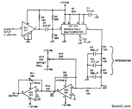
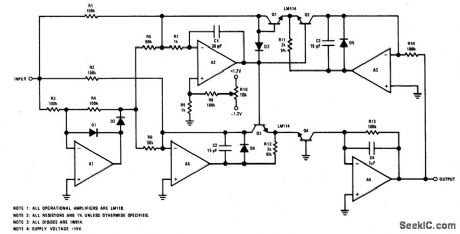
Circuit NotesThe circuit recovers an FM audio signal that varies from less than 1 kHz to about 10 kΗz (View)
View full Circuit Diagram | Comments | Reading(737)
LADDER_ATTENUATOR
Published:2009/6/25 22:51:00 Author:Jessie
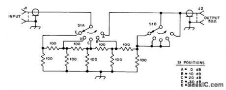
Inserted in series with receiving antenna to provide 5 steps of attenuation for comparing performance of anten-nas or preamps. Resistors are 1/4-W composition with 5% tolerance.-D. DeMaw, What Does My S-Meter Tell Me?, QST, June 1977, p 40-42. (View)
View full Circuit Diagram | Comments | Reading(1464)
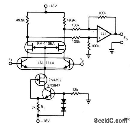
VOLTAGE_CONTROLLED_OPAMP
Published:2009/6/25 22:43:00 Author:May
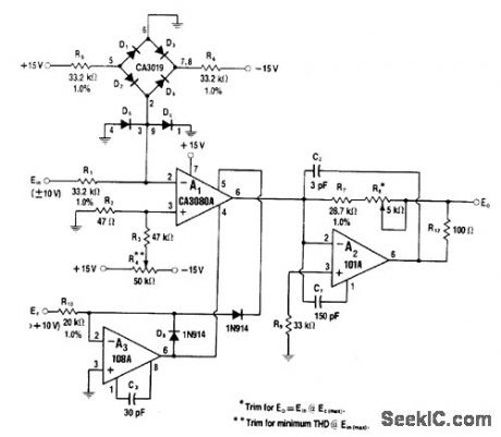
CA3080A operational transconductance amplifier uses bridge to provide automat;c temperature com-pensation of gain that is controlled by voltage between 0 and +10V applied to op amp A3. With values shown, input and output signal-handling range is ±10 V. Once balanced, circuit provides linear gain control up to four decades.-W.G.Jung, IC Op Amp Cookbook, Howard W.Sams, Indianapolis, IN, 1974, p 455-456. (View)
View full Circuit Diagram | Comments | Reading(885)
PLUG_IN_SPEED_CONTROL_FOR_TOOLS_OR_APPLIANCES
Published:2009/6/25 22:43:00 Author:May
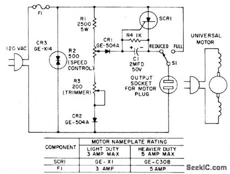
Most standard household appliances and portable hand tools can be adapted to variablespeed operation by use of this simple half-wave SCR phase control. It can be used as the speed control unit for the following typical loads providee they use series universal (brush type) motors.
DrillsFansSewing Machines LathesSaber saws VibratorsPortable band saws Movie projectors Food mixers SandersFood blendersDuring the positive half cycle of the supply voltage, the arm on potentiometer R2 taps off a traction of the sine wave supply voltage and compares it with the counter emf of the motor through the gate of the SCR. When the pot voltage rises above the armature voltage, current flows through CR1 into the gate of the SCR, triggering it, and thus applying the remainder of that half cycle supply voltage to the motor. The speed at which the motor operates can be selected by R2. Stable operation is possible over approximately a 3-to-1 speed range.
(View)
View full Circuit Diagram | Comments | Reading(1230)
DIFFERENTIAL_CASCODE
Published:2009/6/25 22:43:00 Author:May
Direct-coupled single-stage amplifier with differential input and output can be used in one or more stages of high-performance ampimers. Bipolar-JFET caseode arrangement offers significant increase in common-mode input resistance and CMRR as compared to conventional diff erential pair, with little or no degradation of other performance parameters. Differential-mode gain is 116, commdnmode input resistanee is greater than 100 gigohms, CMRR is greaterthan 160 dB, and current-source output resistance is greater than 1 gigohm. Article gives design equations.-R. C.Jaeger and G. A. Hellwarth, Differential Cascode Amplifier Offers Unique Advantages, EDNMag-azine, June 5,1974, p 78 and 80. (View)
View full Circuit Diagram | Comments | Reading(981)
DIRECTION_AND_SPEED_CONTROL_FOR_SERIES_WOUND_MOTORS
Published:2009/6/25 22:49:00 Author:Jessie

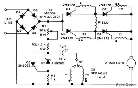
The circuit shown here can be used to control the speed and direction of rotation of a series-wound dc motor. Silicon controlled rectifiers Q1-Q4, which are connected in a bridge arrangement, are triggered in diagonal pairs. Which pair is turned on is controlled by switch St since it connects eithercoupling transformer T1 or coupling transformer T2 to a pulsing circuit. The current in the field can be reversed by selecting either SCRs Q2 and Q3 for conduction, or SCRs Q1 and Q4 for conduction. Since the armature current is always in the same direction, the field current reverses in relation to the armature current, thus reversing the direction of rotation of the motor. A pulse circuit is used to drive the SCRs through either transformer T1 or T2. The pulse required to fire the SCR is obtained from the energy stored in capacitor C1. (View)
View full Circuit Diagram | Comments | Reading(1)
DELAYED_BRAKE
Published:2009/6/25 22:48:00 Author:Jessie
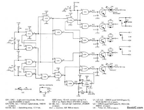
Protects antenna rotator on high tower from damage by delaying brake ac-tion automatically after rotation and by disa-bling direction-selector switches so antenna system coasts to stop before rotation can begin in other direction. For about 3.s delay in timer U4, use 2.2 megohms for R and 1μF for C instead of values shown. RV1 is commonly listed as V150LA20A by GE.S3-S5 are original brake release and direction switches in CDE Hamllrotor system,Article coners construction and installation, including modifications needed Incontrol unit.-A.B,White,A Delayed Brake Release for the Ham-ll,QST, Aug.1977、p14- 16 (View)
View full Circuit Diagram | Comments | Reading(1510)
BOILER_CONTROL
Published:2009/6/25 22:43:00 Author:May
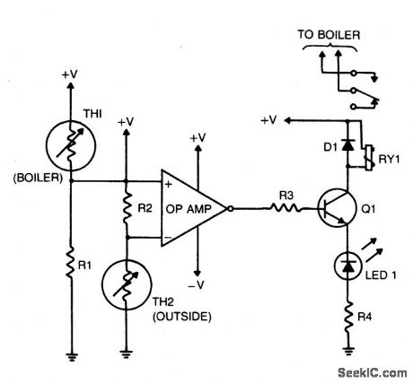
The purpose of this circuit is to control the water temperature in a hot-water heating sys-tem. What it does is to lower the boiler tem-perature as the outside air temperature in-creases. The op amp is used as a comparator. Therrnistor TH2 and R2 form a voltage divider that supplies a reference voltage to the op-amp's inverting input. Thermistor TH2 is placed outdoors, and the values of TH2 and R2 should be chosen so that when the outside temperature is 25 °F, the resistance of the thermistor and resistor are equal. Resistor R1 and thermistor TH1 make up a voltage divider that supplies a voltage to the op amp's nonin-verting input. Thermistor TH1 is placed inside the boiler and the values of TH1 and RI should be chosen so that when the boiler's tempera-ture is 160 °F, their resistances are equal. The output of the op amp controls Q1, which is configured as a transistor switch. When the logic output of the op amp is high, Q1 is turned on, energizing relay RY1. The relay's contacts should be wired so that the boiler's heat supply is turned off (relay energized). (View)
View full Circuit Diagram | Comments | Reading(2346)
10_MHz_WITH_30_dB_GAIN
Published:2009/6/25 22:42:00 Author:May
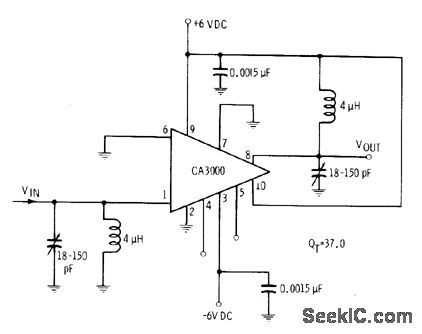
CA3000 IC is operated as RF amplifier with single-ended inputand output, With appropriate tuned circuits, amplifier performs well up to 30MHz,-E.M.Noll,″Linear IC Principles,Experiments, and Projects、″Howard W.Sams.Indianapolis、IN,1974、p91-92 (View)
View full Circuit Diagram | Comments | Reading(830)
80_MHz_WITH_INPUT_PEAKlNG
Published:2009/6/25 22:41:00 Author:May
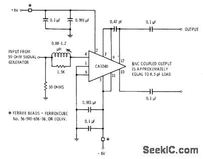
Response of CA3040 video IC is extended beyond 80 MHz in simple circuit that includes adjustable input peaking coil. Response is flatwithin 3 dBto well below t MHz, for gain of about 32 dB.-E. M Noll, Linear IC Principles, Experiments, and Projects, Howard W. Sams, Indianapolis, IN,1974, p163 and 169. (View)
View full Circuit Diagram | Comments | Reading(861)
ELECTRONIC_PHONE_BELL
Published:2009/6/25 22:40:00 Author:May
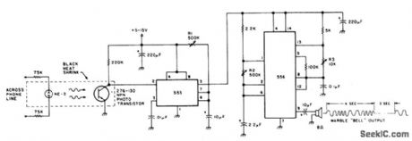
The speaker emits a distinctive warble tone when ring pulses are applied to the phone line. Use this circuit as a remote bell or discon-nect the phone's ringer for direct use. R1 ad-justs the duration of the output; R2 and R3 control the tone's duty cycle and frequency. The transistor is a general-purpose NPN photodevice. The neon bulb and transistor are coupled with the heat-shrink tubing to form an optoisolator. (View)
View full Circuit Diagram | Comments | Reading(859)
TELEPHONE_RINGER_USES_PIEZOELECTRIC_DEVICE
Published:2009/6/25 22:39:00 Author:May
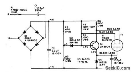
The electronic bell needs no power sup-ply. Most of the resistors are not critical, al-though C2, R2, and R3 work best at the values given. Leaving out RI will make the unit ring louder. The piezo buzzer may vary from store to store. If it has two leads, connect the red lead to the collector and the black lead to the emit-ter of Q1. If a third (blue) lead is present, connect it to the base of Q1. (View)
View full Circuit Diagram | Comments | Reading(871)
MOTOR_SPEED_CONTROL
Published:2009/6/25 22:39:00 Author:May
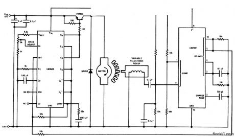
This circuit is a regulating series dc motor speed control using the LM3524 for the control and drive for the motor and the LM2907 as a speed sensor for the feedback network. (View)
View full Circuit Diagram | Comments | Reading(4247)
FAST_HALF_WAVE_RECTIFIER
Published:2009/6/25 22:38:00 Author:May
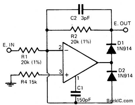
Circuit Notes
Precision half wave rectifier using an op-erational amplifier will have a rectification ac-curacy of 1% from dc to 100 kHz. (View)
View full Circuit Diagram | Comments | Reading(0)
AUTOPATCH_TELEPHONE_LINE_INTERFACE
Published:2009/6/25 22:38:00 Author:May
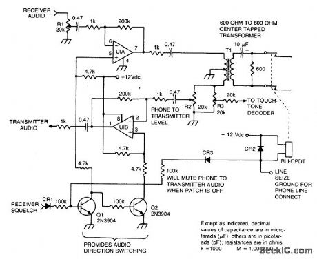
This circuit provides for the receiver-to-phone line and phone line-to-transmitter link, with both using an op amp for gain. (View)
View full Circuit Diagram | Comments | Reading(1840)
PHONE_AUTO_ANSWER_AND_RING_INDICATOR
Published:2009/6/25 22:37:00 Author:May

Ring detect circuit for automatic phone answering or tone generation for reverse autopatch use. (View)
View full Circuit Diagram | Comments | Reading(1415)
RAIN_ALARM/DOOR_BELL
Published:2009/6/25 22:37:00 Author:May
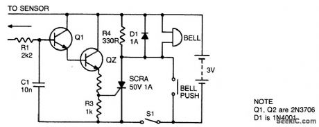
With S1 open the circuit functions as a doorbell. With S1 closed, rain falling on the sensor will turn on Q1, triggering Q2 and the thyristor and activating the bell, R4 provides the holding for the thyristor while D1 prevents any damage to the thyristor from back EMF in the bell coil. The sensor can be made from 3 square inches of copper clad board with a razor cut down the center. C1 prevents any mains pickup in the sensor leads. (View)
View full Circuit Diagram | Comments | Reading(727)
TRUE_RMS_DETECTOR
Published:2009/6/25 22:37:00 Author:May


Circuit Notes
The circuit will provide a dc output equal to the rms value of the input. Accuracy is typi-cally2% for a 20 VPP input signal from 50 Hz to 100 kHz, although it's usable to about 500 kHz.The lower frequency is limited by the size of the filter capacitor. Since the input is dc coupled, it can provide the true rms equivalent of a dc and ac signal. (View)
View full Circuit Diagram | Comments | Reading(0)
LOW_LINE_LOADING_RING_DETECTOR
Published:2009/6/25 22:36:00 Author:May

Low line current loading is provided by the H11BX522 photodarlington op-tocoupler, which provides a 1 mA output from a 0.5 mA input. (View)
View full Circuit Diagram | Comments | Reading(680)
TELEPHONE_HANDSET_TONE_DIAL_ENCODER
Published:2009/6/25 22:35:00 Author:May


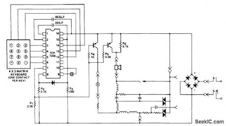
This encoder uses a single contact per key keyboard and provides all other switching func-tion electronically. The diode between termi-nals 8 and 15 prevents the output going more than 1 volt negative tive supply V-. The supply voltage range with respect to the nega-circuit operates over the from 3.5 volts to 15 volts. (View)
View full Circuit Diagram | Comments | Reading(931)
| Pages:1293/2234 At 2012811282128312841285128612871288128912901291129212931294129512961297129812991300Under 20 |
Circuit Categories
power supply circuit
Amplifier Circuit
Basic Circuit
LED and Light Circuit
Sensor Circuit
Signal Processing
Electrical Equipment Circuit
Control Circuit
Remote Control Circuit
A/D-D/A Converter Circuit
Audio Circuit
Measuring and Test Circuit
Communication Circuit
Computer-Related Circuit
555 Circuit
Automotive Circuit
Repairing Circuit