
Circuit Diagram
Index 1283
8_V_FROM_5_V_REGULATOR
Published:2009/6/26 5:05:00 Author:Jessie

If you have trouble locating an 8-V regulator, although they are commonly available, a 5-V unit can replace it by connecting the regulator, as is shown here. (View)
View full Circuit Diagram | Comments | Reading(1101)
OHMMETER
Published:2009/6/26 4:00:00 Author:May
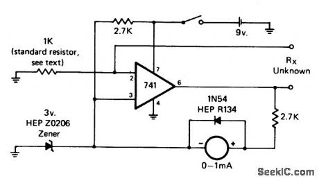
This circuit has a linear reading scale, requires no calibration, and requires no zero adjustment. It may be made multirange by switching in different standard resistors. (View)
View full Circuit Diagram | Comments | Reading(3104)
SWITCHING_REGULATOR_CONVERTER
Published:2009/6/26 4:00:00 Author:May
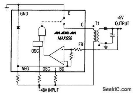
The Max650 switching regulator produces a regulated 5 V from large negative voltages, such as the -48 V found on telephone lines. The resulting power supply operates with several extemal com-ponents, inclucting a transformer, and it delivers 250 mA. The device includes a 140-V 250-mA pnp transistor, short-circuit protection, and all necessary control circuitry. (View)
View full Circuit Diagram | Comments | Reading(901)
02μW_TO_10_mW
Published:2009/6/26 4:00:00 Author:May
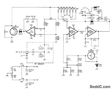
Accurate low-power wattmeter uses small lamps as barretters for measuring RF power up to 10mW from 1 to 500MHz. Applications indude measurements of antenna gain, local oscillator frequency, VSWR, and filter response. Subminiature T-3/4 RF sensor lamps operate in bridge circuit with R1, B2, and R3. Voltage difference between bridge legs is amplified by opamp U1. Bridge current driver Q1 supplies current for balancing bridge. Equilibrium voltage of 3.5 V at VB is fed to metering circuit including U2. Article covers calculation of values for calibration resistors R4-R10, which range from 5.715 to 7192 ohms.-J. H. Bowen, Accurate Low Power RF Wattmeter for High Fre-quency and VHF Measurements, Ham Radio, Dec. 1977, p 38-43. (View)
View full Circuit Diagram | Comments | Reading(859)
WIDEBAND_UHF_AMPLIFIER_WITH_HIGH_PERFORMANCE_FETs
Published:2009/6/26 4:21:00 Author:Jessie
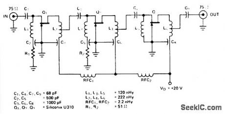
View full Circuit Diagram | Comments | Reading(1076)
ANTENNA_ROTATOR_1
Published:2009/6/26 3:59:00 Author:May
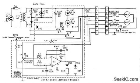
Developed for use with CDE TR-44 antenna control using low-voltage AC motor having pot for bearing indication. Circuit eliminates need for holding control handle in position until antenna reaches desired bearing. Uses 12-VDC 1000-ohm 1-A relays, TISN7274IL opamp U1, and wirewound 360° rotation command pot R7 operating from 14-V regulated supply of original control. When R7 is set to desired new heading, relay applies power to motor for proper direction, and drops out when antenna reaches desired heading. One relay is used for each direction of rotation.Opamp is connected in differential-input mode that responds only to difference voltage between wipers of pots R7 and R8. Polarity of oparnpoutput dependson polarity of input voltage difference. CR3 and CR4 energize K1 or K2 depending on polarity of error signal. R9 and R3 serve to balance voltage difference remaining when R7 and fi8 are at travel limits. R9 also nulls offset present when there is no input to U1. Ac-curacy is about 5°. Diodes are 100-PIV 0.5-A silicon.-K. H. Sucker, Automating the TR-44 An-tenna Rotor, QST, June 1973, p 28-30. (View)
View full Circuit Diagram | Comments | Reading(2535)
600_W_RF_POWER_AMPLIFIER
Published:2009/6/26 4:17:00 Author:Jessie
View full Circuit Diagram | Comments | Reading(1168)
SINGLE_DEVICE,80_W_50_Ohm_VHF_AMPLIFIER
Published:2009/6/26 4:15:00 Author:Jessie
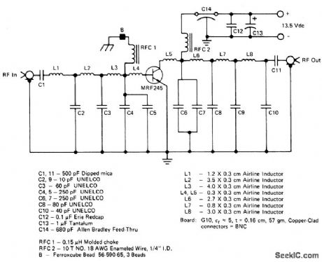
The amplifier uses a single MRF245 and provides 80 W with 9.4 dB galn across the 143 to 156 MHz band. (View)
View full Circuit Diagram | Comments | Reading(3427)
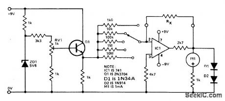
LINEAR_SCALE_OHMMETER_1
Published:2009/6/26 3:59:00 Author:May
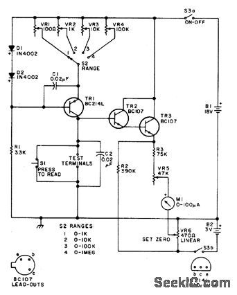
This circuit is designed to provide accu-rate measurement and a linear resistance scale at the high end. The circuit has four ranges.Another meter with a current range of 10 μA to 10 mA and sensitivity of 10,000 ohms per volt is needed for setting up. (View)
View full Circuit Diagram | Comments | Reading(0)
ADJUSTABLE_20_V_SUPPLY
Published:2009/6/26 3:59:00 Author:May
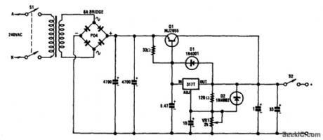
This circuit can deliver 3 A or more and a maximum dc voltage of a little over 20 V. It is designed around the readily available LM317T adjustable 3-terminal regulator and has a pnp power transistor to boost the current output.
The transformer has an 18-V secondary rated at 6 A; this feeds to bridge rectifier and two 4700-μF capacitors to yield around 25 Vdc. This voltage is fed to the emitter of the MJ2955 transistor and to the input of the LM317 via a 33-Ω resistor. (View)
View full Circuit Diagram | Comments | Reading(2073)
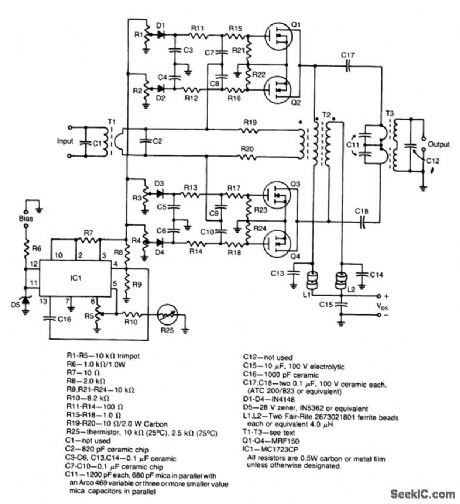
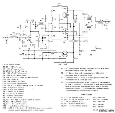
80_W_PEPBROADBAND_LINEAR_AMPLIFIER
Published:2009/6/26 4:14:00 Author:Jessie
View full Circuit Diagram | Comments | Reading(721)
V_F_CONVERTER
Published:2009/6/26 3:56:00 Author:May
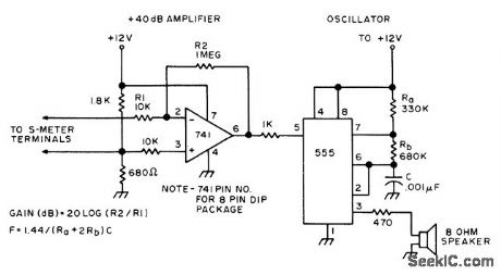
Voltage developed across Smeter is amplified by 741 opamp having gain of 40 dB so full.scale voltage of 100mV becomes 10V at opamp outptit. This drives modulation input of 555 timer connected as freerunning oscillator. Nominal 1-kHz output increases in frequency as drive current is reduced; conversely, drop in frequency corresponds to stronger signal at S-meter. Developed for use as audible guide when tuning Yagi and other beam antennas for amateur radio operation.-G.Hinkle, Closed Loop Antenna Tuning, 73 Magazine, May 1976, p 32-33. (View)
View full Circuit Diagram | Comments | Reading(1)
LAPTOP_COMPUTER_POWER_SUPPLY
Published:2009/6/26 4:13:00 Author:Jessie
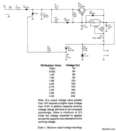
A laptop computer supply that has 9-V output, crowbar overvoltage protection, and operates from a 12-V supply is shown above. The supply voltage should be at least 3.6 V above the expected output voltage. Q1 should be heatsinked appropriately.R5 should have a value of 1.5 kΩ for 9-V out-put. Table 1 gives values for other voltages. (View)
View full Circuit Diagram | Comments | Reading(1051)
VOLTAGE_DOUBLER_SUPPLY
Published:2009/6/26 3:56:00 Author:May
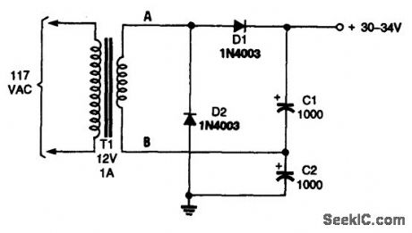
The voltage doubler is built around a pair of diodes (D1 and D2) and a pair of capacitors (C1 and C2) that are fed from, in this case, a 12-V, 1-A step-down transformer (T1). (View)
View full Circuit Diagram | Comments | Reading(764)
160_W_PEP_BROADBAND_LINEAR_AMPLIFIER
Published:2009/6/26 4:13:00 Author:Jessie
View full Circuit Diagram | Comments | Reading(1146)
BRIDGE_CIRCUIT
Published:2009/6/26 3:55:00 Author:May
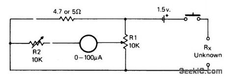
For measurement of resistances from about 5 ohms down to about 1/10 ohm. (View)
View full Circuit Diagram | Comments | Reading(0)
140_W_PEP_AMATEUR_RADIO_LINEAR_AMPLIFIER_2_30_MHz
Published:2009/6/26 4:12:00 Author:Jessie

This inexpensive, easy to construct amplifier uses two MRF454 devices. Specified at 80 w power output with 5 W of input drive, 30 MHz, and 12.5 Vdc. (View)
View full Circuit Diagram | Comments | Reading(822)
0_TO_12_V,_1_A_VARIABLE_POWER_SUPPLY
Published:2009/6/26 3:55:00 Author:May
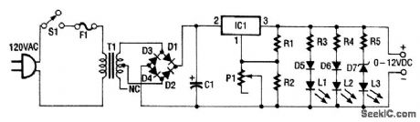
This 0- to 12-Vdc variable power supply uses an IC voltage regulator and a heavy-duty trans-former to provide a reliable dc power supply. Looking at the schematic shown, you can see that transformer T1 has a 120-V primary and a 28-V secondary.
Filtered dc is fed to the input (pin 2) ofthe LM317T voltage regulator, IC, which keeps the volt-age at its output constant (pin 3) regardless (within limitations) of the input voltage. Pin 1 of the LM317T is the adjustment pin. Varying the voltage on pin 1 (via P1) varies the output voltage.
Diodes D5 through D7 and LEDs L1 through L3 give an approximate indication of the output voltage. Each LED/diode path has a limiting resistor to limit the current to a level that is safe for the LED. (View)
View full Circuit Diagram | Comments | Reading(1323)
LINEAR_SCALE_OHMMETER
Published:2009/6/26 3:55:00 Author:May


One preset resistor is used for all the ranges, simplifying the setting up. Diode clamping is included to prevent damage to the meter if the unknown resistor is higher than the range selected. When the meter has been assembled, a 10 K precision resistor is placed in the test position, R,; the meter is set to the 10 K range and RV1 is adjusted for full scale deflection. (View)
View full Circuit Diagram | Comments | Reading(2039)
138_Vdc_2_A_REGULATED_POWER_SUPPLY
Published:2009/6/26 3:53:00 Author:May
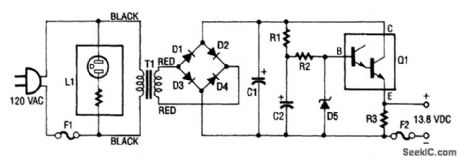
This regulated power supply consists of step-down transformer T1, a full-wave rectifier bridge (D1 through D4), and a filtering regulator circuit made up of C1, C2, R1, R2, R3, D5, and Q1. When 120 Vac is provided, the neon-lamp assembly L1 lights up, and transformer T1 changes 120 Vac to about 28 Vac. The rectifier bridge, D1 through D4, rectifies the ac into pulsating dc, which is then fil-tered by C1. Capacitor C1 acts as a storage capacitor. Zener diode D5 keeps the voltage constant across the base of Darlington regulator Q1, causing constant voltage across resistor R3 and the (+) and (-) output terminals, where the load is connected. Fuse F2 is used to open ( blow ), if the cur-rent through the output terminals is too high. Make sure to take proper precautions when using projects powered by 120 Vac. (View)
View full Circuit Diagram | Comments | Reading(1208)
| Pages:1283/2234 At 2012811282128312841285128612871288128912901291129212931294129512961297129812991300Under 20 |
Circuit Categories
power supply circuit
Amplifier Circuit
Basic Circuit
LED and Light Circuit
Sensor Circuit
Signal Processing
Electrical Equipment Circuit
Control Circuit
Remote Control Circuit
A/D-D/A Converter Circuit
Audio Circuit
Measuring and Test Circuit
Communication Circuit
Computer-Related Circuit
555 Circuit
Automotive Circuit
Repairing Circuit