
Circuit Diagram
Index 1289
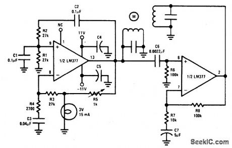
TWO_PHASE_MOTOR_DRIVE
Published:2009/6/26 1:48:00 Author:May
View full Circuit Diagram | Comments | Reading(576)
DIRECTION_AND_SPEED_CONTROL_FOR_SHUNT_WOUND_MOTORS
Published:2009/6/26 1:47:00 Author:May
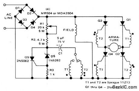
This circuit operates like the one shown in Fig. 57-4. The only differences are that the field is placed across the rectified supply and the armature is placed in the SCR bridge. Thus the field current is unidirectional but armature current is reversible; consequently the motor's direction of rotation is reversible. Potentiometer R1 controls the speed. (View)
View full Circuit Diagram | Comments | Reading(1)
SPEED_CONTROL_FOR_MODEL_TRAINS_OR_CARS
Published:2009/6/26 1:46:00 Author:May
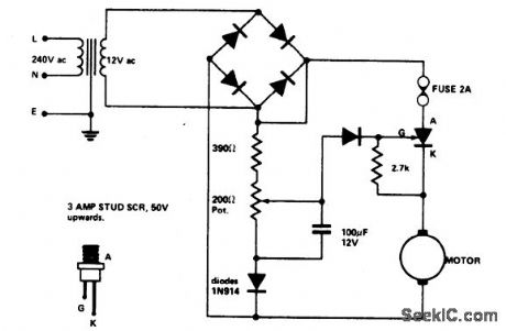
Low voltage speed control gives very good starting torque and excellent speed regulation. A reversing switch may be incorporated in the leads to the motor. (View)
View full Circuit Diagram | Comments | Reading(709)
UNIVERSAL_MOTOR_CONTROL_WITH_BUILT_IN_SELF_TIMER
Published:2009/6/26 1:45:00 Author:May
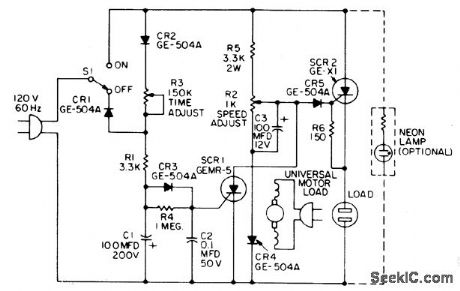
When the time delay expires, SCR1 conducts and removes the gate signal from SCR2, which stops the motor. Both the time delay and motor speed are adjustable by potentiometers R2 and R3. If heavier motor loads are anticipated, use the larger C30B SCR in place of the GE-X1 for SCR2. Also, the capacitance of C1 can be increased to lengthen the tinie delay, if desired. (View)
View full Circuit Diagram | Comments | Reading(1623)
1DC_MOTOR_SPEED_CONTROL
Published:2009/6/26 1:43:00 Author:May
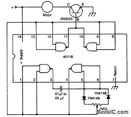
The circuit uses a 4011 CM0S NAND gate, a pair of diodes and an NPN power transistor to provide a variable duty-cycle dc source. Adjusting the speed control varies the average voltage applied to the motor. The peak voltage, however, is not changed. This pulse power is effective at very low speeds, constantly kicking the motor along. At higher speeds, the motor behaves in a nearly normal manner. (View)
View full Circuit Diagram | Comments | Reading(874)
DIFFERENTIAL_THERMOMETER
Published:2009/6/26 1:43:00 Author:May
View full Circuit Diagram | Comments | Reading(0)
1INDUCTION_MOTOR_CONTROL
Published:2009/6/26 1:42:00 Author:May
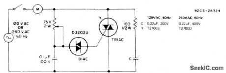
This single time-constant circuit can be used as proportional speed control for induction motors such as shaded pole or permanent split-capacitor motors when the load is fixed. The circuit is best suited to applications which require speed control in the medium to fullpower range. (View)
View full Circuit Diagram | Comments | Reading(2132)
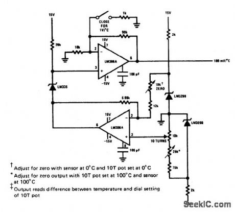
VARIABLE_OFFSET_THE_RMOMETER
Published:2009/6/26 1:42:00 Author:May
View full Circuit Diagram | Comments | Reading(633)
DIGITAL_THERMOMETER
Published:2009/6/26 1:41:00 Author:May
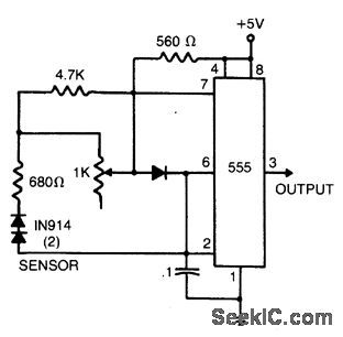
The sensor consists of two series-connected 1N914s, part of the circuit of a 555 multivibrator. Wired as shown, the output pulse rate is proportional to the temperature of the diodes. This output is fed to a simple frequency-counting circuit. (View)
View full Circuit Diagram | Comments | Reading(806)
ISOLATED_TEMPERATURE_SENSOR
Published:2009/6/26 1:40:00 Author:May
View full Circuit Diagram | Comments | Reading(2)
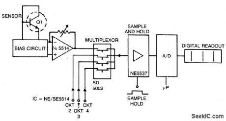
μP_CONTROLLED_DIGITAL_THERMOMETER
Published:2009/6/26 1:39:00 Author:May
View full Circuit Diagram | Comments | Reading(988)
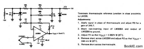
CENTIGRADE_CALIBRATED_THERMOCOUPLE_THERMOMETER
Published:2009/6/26 1:38:00 Author:May
View full Circuit Diagram | Comments | Reading(1139)
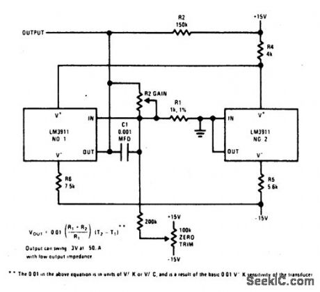
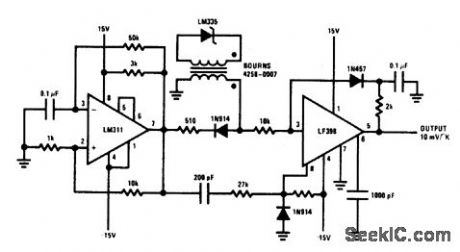
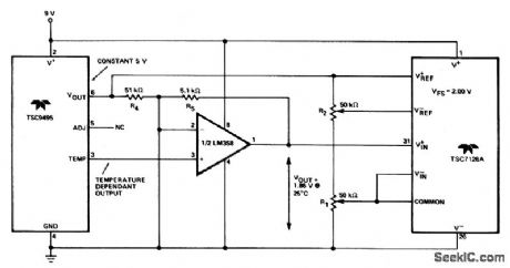
PRECISION_TEMPERATURE_TRANSDUCER_WITH_REMOTE_SENSOR
Published:2009/6/26 1:37:00 Author:May
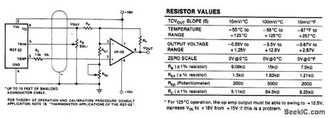
View full Circuit Diagram | Comments | Reading(1172)
INTEGRATED_CIRCUIT_TEMPERATURE_SENSOR
Published:2009/6/26 1:36:00 Author:May
View full Circuit Diagram | Comments | Reading(1004)
TEMPERATURE_SENSOR
Published:2009/6/26 1:35:00 Author:May
View full Circuit Diagram | Comments | Reading(3221)
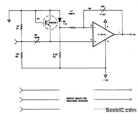
FOUR_CHANNEL_TEMPERATURE_SENSOR(0_50℃)
Published:2009/6/26 1:34:00 Author:May
View full Circuit Diagram | Comments | Reading(832)
TEMPERATURE_METER
Published:2009/6/26 1:33:00 Author:May
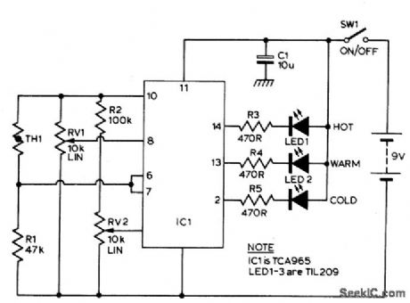
TCA965 window discriminator IC allows the potentiometers RV1 and RV2 to set up a window height and window width respectively. R1 and thermistor TH1 for a potential divider connected across the supply lines. RI is chosen such that at ambient temperature the voltage at the junction of these two components will be approximately half supply. As the temperature of the sensor changes, the voltage will change. RV1 will set the point which corresponds to the center voltage of a window the width of which is set by RV2. The switching points of the IC feature a Schmitt characteristic with low hys-teresis. The outputs of IC1 indicate whether the input voltage is within the window or out-side by virtue of being either too high or too low. The outputs of IC1 drive the LEDs via a current limiting resistor. (View)
View full Circuit Diagram | Comments | Reading(2002)
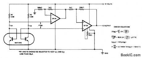
LINEAR_TEMPERATURE_TO_FREQUENC_Y_TRANSCONDUCER
Published:2009/6/26 1:31:00 Author:May
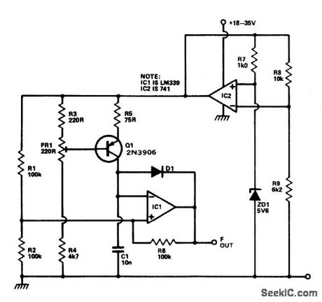
This circuit provides a linear increase of frequency of 10 Hz/℃ over 0-100 ℃ and can thus be used with logic systems, including mi-croprocessors. Temperature probes Q 1 Vb. changes 2.2 mV/℃. This transistor is incorpo-rated in a constant current source circuit. Thus, a current proportional to temperature will be available to charge C1. The circuit is powered via the temperature stable reference voltage supplied by the 741. Comparator IC1 is used as a Schmitt trigger whose output is used to dis-charge C1 via D1 To calibrate the circuit Q1 is immersed in boiling distilled water atad PR1 adjusted to give 1 kHz output. The prototype was found to be accurate to within 0.2 ℃. (View)
View full Circuit Diagram | Comments | Reading(1079)
WIND_ACTIVATED_CONTROL
Published:2009/6/25 23:47:00 Author:May
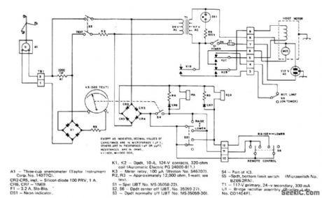
Anemometer feeding meter relay energizes control relay for antenna-tower hoist motor, to lower tower au-tomatically when wind exceeds preset safe speed and raise it again when wind drops well below danger level. When only K1 is energized, motor rotates in tower-lowering direction.When K1 and motor-reversing relay K2 are both energized, motor reverses and raises tower.-J.Bernstein, The Tower-Guard System, QST 1974,p 25-28 (View)
View full Circuit Diagram | Comments | Reading(1801)
SWR_T0_500_MHz
Published:2009/6/25 23:47:00 Author:May
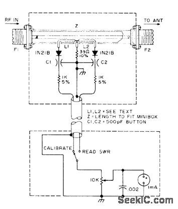
Permits measuring standing-wave ratio well above limits of many inex-pensive indicators. Fot transmitters up to 2 W, coupling loop L1-L2 can be about 1 inch long.For high-power transmitters, loop length can be reduced to about 1/8 inch.-W. E. Parker, UHF SWR Indicator, 73 Magazine, June 1977, p 68-70. (View)
View full Circuit Diagram | Comments | Reading(2267)
| Pages:1289/2234 At 2012811282128312841285128612871288128912901291129212931294129512961297129812991300Under 20 |
Circuit Categories
power supply circuit
Amplifier Circuit
Basic Circuit
LED and Light Circuit
Sensor Circuit
Signal Processing
Electrical Equipment Circuit
Control Circuit
Remote Control Circuit
A/D-D/A Converter Circuit
Audio Circuit
Measuring and Test Circuit
Communication Circuit
Computer-Related Circuit
555 Circuit
Automotive Circuit
Repairing Circuit