
Circuit Diagram
Index 803
Norton_free_running_staircase_generator
Published:2009/7/17 4:34:00 Author:Jessie

This circuit uses four sections of an LM3900 to form a free-running staircase generator. When the output exceeds about 80% of V+, a 100-μs reset pulse is generated, and the staircase output is caused to fall to about zero volts. The next pulse from amplifier I then starts a new stepping cycle. National Semiconductor, Linear Applications Handbook 1991, p 236 (View)
View full Circuit Diagram | Comments | Reading(983)
CURRENT_AMPLIFIER
Published:2009/7/10 21:44:00 Author:May

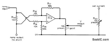
Used in FET curve input tracer to amplify drain current passing through R14, sufficiently to give required Y output for oscilloscope. Uses SN72741P opamp as difference amplifier. Article gives other circuits of curve tracer and calibration procedure.-L. G. Cuthbert, An F.E.T. Curve Tracer, Wireless World,April 1974, p 101-103. (View)
View full Circuit Diagram | Comments | Reading(1176)
WIND_CHILL_METER
Published:2009/7/10 21:38:00 Author:May
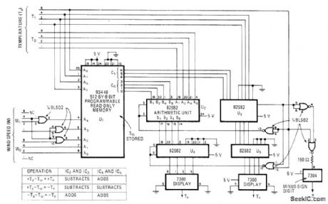
Circuit measures and displays wind-chill equivalent temperature by combining air temperature and wind speed data. PROM is programmed to act in combination with arithmetic-logic units to generate output values corresponding to those of wind-chill temperature chart adopted by National Weather Service. Article gives Iisting of PR0M contents.-V. R. Clark, PROM Converts Weather Data for Wind-Chill Index Display, Electronics, Jan. 5, 1978, p 158-159. (View)
View full Circuit Diagram | Comments | Reading(1155)
FIVE_RANGES_TO_1μF_WITH_TIMERS
Published:2009/7/10 21:37:00 Author:May
Based on fact that output pulse width of 555timer varies linearly with value of timing capacitance used. If timer is triggered with constant frequency, average DC value of resulting pulse train is linear function of pulse width. DC meter then reads capacitance values linearly. Decade capachance ranges are obtained by switching value of timing resistor. Trimpot for each range is adjusted for zero meter reading when push-button is pressed, without test capacitor,-C. Hall, Simplified Capacitance Meter, Ham Radio, Nov. 1978, p 78-79. (View)
View full Circuit Diagram | Comments | Reading(623)
ELECTROMETER_FEEDBACK_AMPLIFIER
Published:2009/7/17 4:33:00 Author:Jessie
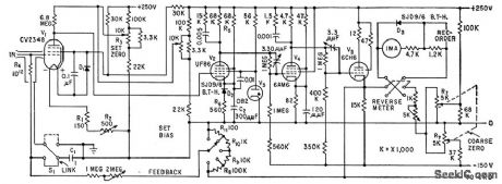
Measures currents in range of 10-11 to 10-15 amp by passing current through high-value precision resistor and amplifying voltage drop across resistor with direct-coupled amplifier of electrometer. British CV2348 is similar to CK5886. Bandwidth is 7.5 Mc. Zener diode D3 provides meter overload protection by damping at about 20% overload.-D. Allenden, Using Feedback in Electrometer Design, Electronics, 32:41, p 71-73. (View)
View full Circuit Diagram | Comments | Reading(1795)
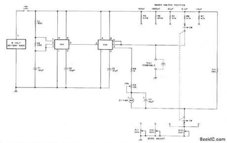
DUAL_TIMER_MEASURES_C
Published:2009/7/10 21:37:00 Author:May
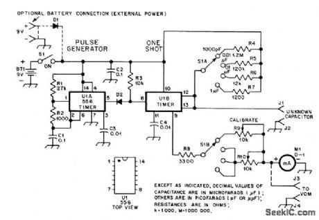
One section of U1 (two 555s in single package) is connected as oscillator that serves as trigger for other section (U1B). Ratio of R1 and R2 determines length of pulse generated during each oscillation cycle, while C1 and same resistors set frequency at about 500 Hz. U1B produces predetermined-duration output pulse for each start pulse regard-less of starting pulse length. Pulse duration is set by R4-R7 and external capacitor being measured. Smaller capacitor in given range produces shorter output pulse from U1B mono MVBR. Average pulse power increases with pulse length and increases meter reading linearly so capacitance value is indicated directly.Values shown give ranges of 1000 pF, 0.01 μF, 0.1μF, and 1 μF full-scale. R10 serves as calibration resistor for all three higher scales. D1 is 50-PIV or higher silicon power-type diode, and D2 is 1N914 or equivalent.-D. A. Blakeslee, An inexpensive Capacitance Meter, OST, Sept.1978, p 11-14 and 37. (View)
View full Circuit Diagram | Comments | Reading(712)
MATCHED_TRANSISTOB_SENSOR
Published:2009/7/10 21:35:00 Author:May
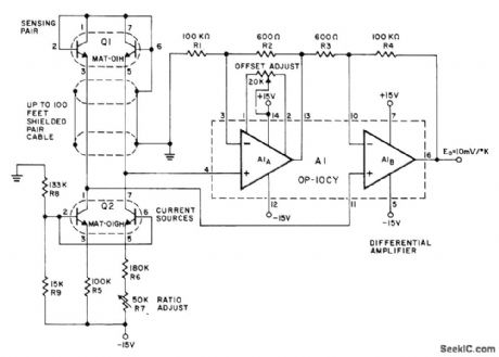
Precision Monolithics MAT-01H matched-tlansistor pair Q1 senses temperature over range of -55℃ to +125℃ with inherent linearity and long-term stability. Matched transistors Q2 (MAT-01GH) are current sources for sensing transistors. Transistol combination provides diffelential voltage output that is directly proportional to absol ute temperatu re. Amplifier using OP-10CY changes this voltage difference to single-ended signalthatcan be used for measurement orcontrol. Circuit will drive 10-V full-scale digital panel meter to give digital thermometer.-J. Simmons and D. Soderquist, Temperature Measurement Method Based on Matched Tran-sistor Pair Requires No Reference, Precision MonolithIcs, Santa Clara, CA, 1975, AN-12, p 4. (View)
View full Circuit Diagram | Comments | Reading(1188)
STRONG_NOISE_SUPPRESSING_AUDIO_AMPLIFIER
Published:2009/7/17 4:33:00 Author:Jessie

Feedback circuit limits amplitude of low-frequency signals such as those produced by wind-moved tree branches, to prevent masking vehicular target signals in portable doppler radar. Low-pass filtering compensates for poor bass response of human ear permitting detection of slow-moving targets such as walking man.-J. Scott, D. Randise, and R P. Lukacovic, Portable Radar Traces Battlefield Deployment, Electronics, 33:12, p 67-70.
(View)
View full Circuit Diagram | Comments | Reading(725)
Norton_slow_sawtooth_waveform_generator
Published:2009/7/17 4:32:00 Author:Jessie
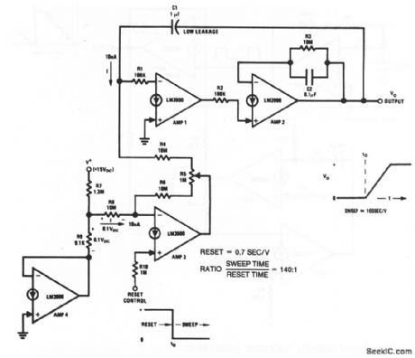
This circuit uses four sections of an LM3900 to form a generator with very slow sawtooth waveforms (which can be used to generate long time-delay intervals, as one application). The reset signal is applied to amplifier 3 through R10, and R5 adjusts the sweep. With the values shown, the 10-nA current and 1-μF capacitor establishes a sweep rate of 100 s/V. R4 provides a reset rate of 0.7 s/V.National Semiconductor, Linear Applications Handbook, 1991 p 234. (View)
View full Circuit Diagram | Comments | Reading(915)
RESISTANCE_COMPARATOR
Published:2009/7/17 4:32:00 Author:Jessie
Known and unknown resistances are connected alternately, across shock-excited oscillator by flip-flopdriven relay, and damping effect is observed on cro.-A. Kislovsky, Comparing Resistances with Oscillator and Oscilloscope, Electronics, 34:23, p 118. (View)
View full Circuit Diagram | Comments | Reading(1314)
TELEPHONE_OPERATED_ac_POWER_SWITCH
Published:2009/7/10 21:35:00 Author:May
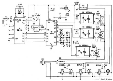
Tones (from the DTMF) on the telephone line are detected by U1. When a valid tone is received, pin 14 (D/V) of U1 produces a positive pulse that is used to drive NAND gates U2A and U2B and then to latch binary data from U1 into Quad-D flip-flop U3 (U1 could be decoded into 16 bits, if required). The Q outputs of U3 drive optoisolators that control triacs TR1, TR2, and TR3. PS1 is a 6-V 150-mA dc adapter that operates from 120 Vac. (View)
View full Circuit Diagram | Comments | Reading(1441)
DISTANCE_MARK_GENERATOR_1
Published:2009/7/17 4:32:00 Author:Jessie
Uses switched Hartley oscillator, mvbr-type trigger shaper, and parallel-triggered blocking oscillator to generate distance marks in airborne search radar. RLC unit is switched to change mark spacting.-NBS, Handbook Preferred Circuits Navy Aeronautical Electronic Equipment, Vol. 1, Electron Tube Circuits, 1963, p N8-1. (View)
View full Circuit Diagram | Comments | Reading(637)
ALPHA_CUTOFF
Published:2009/7/17 4:31:00 Author:Jessie
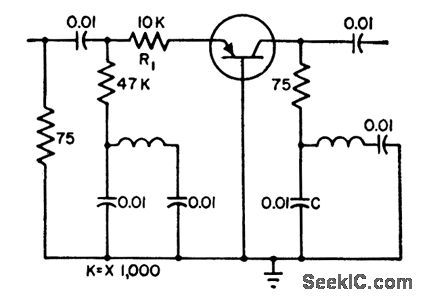
Measured with 3% accuracy up to 30 Mc and 5% up to 100Mc.Method compares transistor to short-circuit.-G. I. Turner, Measuring Transistor Alpha Cutoff, Electronics, 32:1, p 54. (View)
View full Circuit Diagram | Comments | Reading(1141)
HOT_COLD_METER
Published:2009/7/10 21:33:00 Author:May
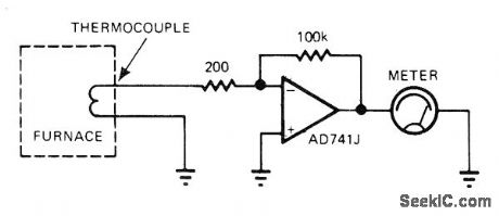
Output of unreferenced thermocouple dfives meter through opamp that provides required gain, for monitoring temperature inside furnace when exact temperature value is not required. Meter is simply calibrated in terms of hot and cold.-J. Williams, Designer's Guide to: Temperature Measurement, EDN Magazine, May 20, 1977, p 71-77. (View)
View full Circuit Diagram | Comments | Reading(1159)
Norton_triangle_wave_generator
Published:2009/7/17 4:30:00 Author:Jessie

This circuit uses one section of an LM3900 to form a triangle-wave generator. Notice that the circuit also produces a square-wave output at the same frequency. National Semiconductor Linear Applications Handbook, 1991, p 233 (View)
View full Circuit Diagram | Comments | Reading(1158)
05_pF_TO_0001μF_COMPARATOR
Published:2009/7/10 21:32:00 Author:May
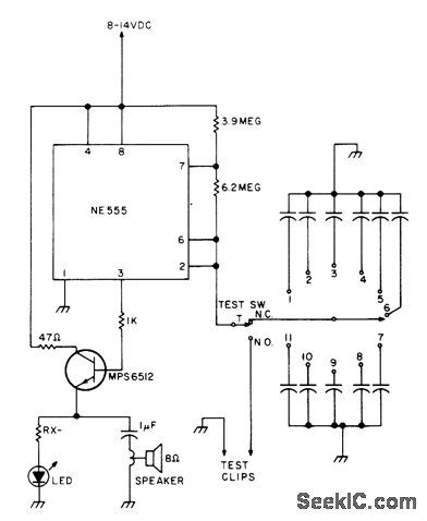
Provides audio-tone comparison of built-in reference capacitor to unknown capacitor connected between test clips. Frequency of tone is about 8 kHz for 0.5 pF, dropping to 100 Hz as capacitor value goes up to 0.001μF. Larger capacitor values merely turn LED on and off; 0.1 μF gives flashing atabout 5 Hz. Any NPN audio orswitching transistorcan be used in place of MPS6512. Suggested reference values for capacitor bank are 0.7, 3, 5, 10, 25, 50, 100, 330, 470, 680, and 820 pF.-W. Pinner, The Capacitor Comparator, 73 Magazine, March 1977, p 49. (View)
View full Circuit Diagram | Comments | Reading(645)
C_BY_GRID_DIP
Published:2009/7/10 21:31:00 Author:May
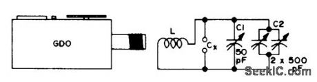
Values of unknown capaci-tances up to about 1000 pF can be measured with simple circuit used with griddip oscillator.Coil L can be 6 turns of stiff wire, To calibrate, close variable capacitors C1 and C2 fully, tune for dip, and note dip frequency at pointer position of C2. Now connect known capacitors up to 1000 pF one by one to CX, retune C2 for dip, and mark capacitor value on C2 dial. Close C2, then repeat calibration for C1 while using smaller capacitors up to 50 pF.-F, G. Rayer, GDO to Find C, 73 Magazine, Aug. 1974, p 35. (View)
View full Circuit Diagram | Comments | Reading(617)
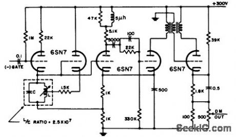
VARIABLE_SWEEP_LENGTH
Published:2009/7/17 4:30:00 Author:Jessie

Operates with sweep lengths varying by factor of 8 to 1. Supplies 1,100 v at 160 ma for 0.5-mile range and 400 v at 270 ma for 4-mile range.-R. F. P. Smith, Airport Radar Has High Resolution, Electronics, 32:14, p 64-69. (View)
View full Circuit Diagram | Comments | Reading(764)
12-V_AUTO_POWERED_CIRCUIT_FOR_CASSETTE_RECORDERS
Published:2009/7/10 21:31:00 Author:May
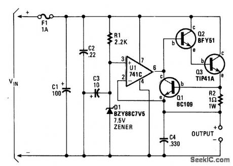
A regulator allows you to power a 7.5-V cassette recorder or other device from a 12-Vdc auto system. About 600 mA is available from the circuit. Q3 should be heatsinked because it dissipates up to 4 W. F1 should be a slow-blow fuse so that the surge caused by C1 does not cause unnecessary fuse failures. (View)
View full Circuit Diagram | Comments | Reading(666)
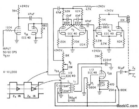
MEASURING_NEGATIVE_RESISTANCE_OR_TD
Published:2009/7/17 4:30:00 Author:Jessie
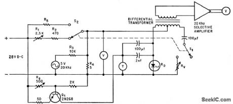
Thermistor cancels negative resistance of tunnel diode, and calibrated potentiometer that matches thermistor gives absolute value of td resistance at operating point. Q1 pro vides thermistor heating current, at level set by R6, while 5-v, 20-kc source provides ac to modulate bias of tunnel diode.-A.Ambrozy, Thermistor Measures Negative Resistance of Tunnel Diode, Electronics, 39:17, p 95-96.
(View)
View full Circuit Diagram | Comments | Reading(849)
| Pages:803/2234 At 20801802803804805806807808809810811812813814815816817818819820Under 20 |
Circuit Categories
power supply circuit
Amplifier Circuit
Basic Circuit
LED and Light Circuit
Sensor Circuit
Signal Processing
Electrical Equipment Circuit
Control Circuit
Remote Control Circuit
A/D-D/A Converter Circuit
Audio Circuit
Measuring and Test Circuit
Communication Circuit
Computer-Related Circuit
555 Circuit
Automotive Circuit
Repairing Circuit