
Circuit Diagram
Index 809
SQUELCH_ACTUATED_MOBILE_REPEATER
Published:2009/7/17 9:45:00 Author:Jessie
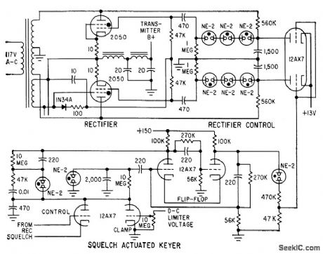
Thyratrons serve as rectifiers in transmitter power supply to avoid repeater malfunctions caused by relays. When incoming signal opens receiver squelch, thyratrons conduct and provide d-c power for transmitter. Under standby conditions, flip-flop keeps thyratrons nonconducting. When relaxation oscillator is activated by squelch tube voltages, flip-flop reverses and applies pulses to thyratrons to make them conduct. This prevents transmitter from being activated by receiver failure.-L. G. Sands, Design Trends in Mobile Radio Repeaters, Electronics, 32:47, p 82-84. (View)
View full Circuit Diagram | Comments | Reading(1297)
BANG_BANG_CONTROLLERS
Published:2009/7/10 20:32:00 Author:May
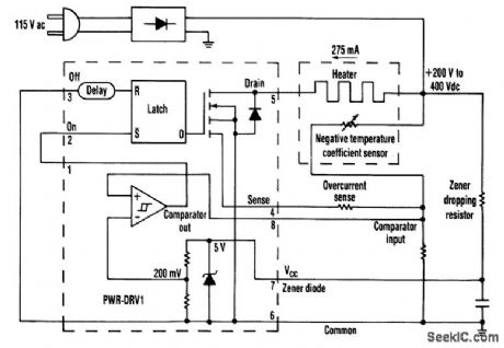
Just one chip, the PWR-DRV1 from Power Integrations, builds a bang-bang controller that switches 275 mA and runs off the rectified 115-Vac mains. An on-chip zener diode powers the chip from high voltage through a dropping resistor. (View)
View full Circuit Diagram | Comments | Reading(767)
LOW_NOISE_AMPLIFIER_DESIGN
Published:2009/7/17 9:42:00 Author:Jessie
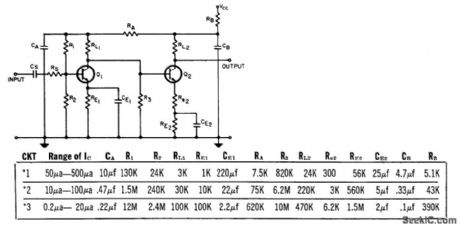
Article gives design procedure based on use of contour maps for 2N2524 at 100 cps, 1 kc, and 10 kc. Goal of design is to confine overall amplifier noise to that of transistor in first stage. Component values are given for three different low-noise amplifiers, each operating in a different range of collector current. -J. W. Baker, Jr., Designing Low Noise Amplifiers from Noise-Figure Contours, EEE, 11:10, p 56-59. (View)
View full Circuit Diagram | Comments | Reading(1101)
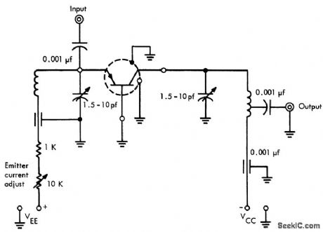
1000_MC_TO_200_MC_CONVERTER
Published:2009/7/17 9:24:00 Author:Jessie
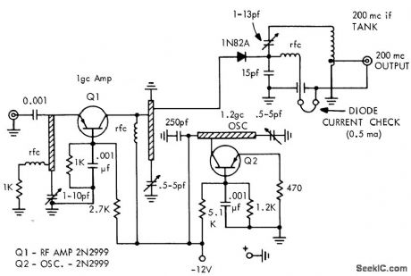
Used in measuring transistor noise figure at 1,000 Mc. Oscillator of converter operates at 1,200 Mc. Converter has gain of 10 db and 5 db noise figure.-Texas Instruments Inc., Solid-State Communications, McGraw-Hill, N.Y., 1966, p 349. (View)
View full Circuit Diagram | Comments | Reading(710)
DEVIATION_METER
Published:2009/7/10 20:32:00 Author:May
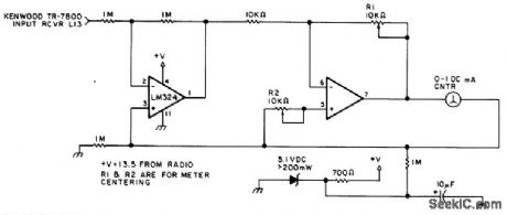
You can use this circuit in most FM VHF receivers; the hookup is off the FM discriminator.Because every signal transmitted has its own deviation signature,this can be a red plusin hunting jammers. (View)
View full Circuit Diagram | Comments | Reading(0)
AMPLITUDE_PROBABILITY_DENSITY_FUNCTION
Published:2009/7/17 9:22:00 Author:Jessie
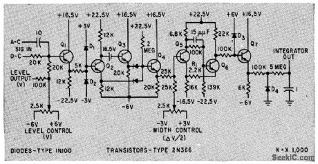
Width of output pulse is proportional to time that input signal is between specified voltage levels. Used in statistical measurements of signals and noise.-B. M. Rosenheck, Detecting Signals By Polarity Coincidence, Electronics, 33:5, p 67-69. (View)
View full Circuit Diagram | Comments | Reading(1025)
WIDEBAND_TEST_AMPLIFIER
Published:2009/7/10 20:20:00 Author:May

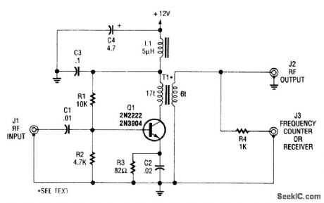
This single-stage amplifier (using a 2N2222 or 2N3904 general-purpose transistor) is useful for interfacing test instruments,T1 is an Amidon Associates FT-23-43 core wound with 17 and 6 turns of #26 wire,J3 isa lower-level output for a momtonng device(such as a recelver frequency counter or spectrum analyzer).
(View)
View full Circuit Diagram | Comments | Reading(2985)
LOW_COST_STEREO_PHONOGRAPH
Published:2009/7/10 6:20:00 Author:May
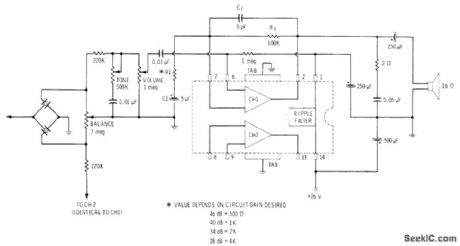
Uses single Sprague ULN-2277 IC containing two audio amplifiers each capable of driving loudspeaker directly, for input from high-impedance stereo cartridge Connections are identical for other channel,Power output per channel is 2 W. Tone and volume controls ale ganged, with those for other channel, but balance control shown serves both channels.-E. M. Noll, Linear IC Principles, Experiments, and Projects, Howard W. Sams, Indianapolis, IN, 1974, p 237-239. (View)
View full Circuit Diagram | Comments | Reading(895)
PLL_STEREO_FM_DEMODULATOB
Published:2009/7/10 6:19:00 Author:May
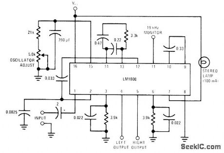
National LM1800 IC uses phase-locked loop techniques to regenerate 38-kHz subcarrier. Automatic stereo/monaural switching is included. Supply voltage range is 10-18 V.- LM1800 Phase Locked Loop FM Stereo Demodulator, National Semiconductor, Santa Clara, CA, 1974. (View)
View full Circuit Diagram | Comments | Reading(1057)
PLL_DECODER
Published:2009/7/10 6:19:00 Author:May
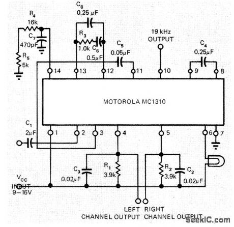
Motorola MC1310 phase-locked loop stereo decoder requires only one adjustment, by 5K pot R5. With pin 2 open, adjust R5 until reading of 19.00 kHz is obtained with frequency counter at pin 10. Alternatively, tune to stereo broadcast and adjust R5 to center of lock-in range of stereo pilot lamp. Circuit gives 40-dB separation and about 0.3% total harmonic distortion.-B. Korth, Phase-Locked Loop Stereo Decoder is Aligned Easily, EDN Magazine, Jan. 20, 1973, p 95. (View)
View full Circuit Diagram | Comments | Reading(2791)
LOUDSPEAKER_PHASING
Published:2009/7/10 6:18:00 Author:May
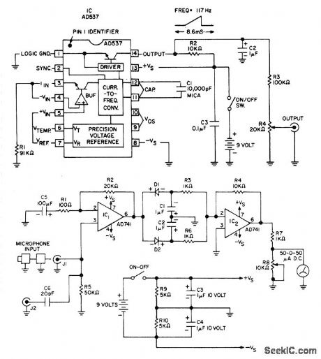
Used to determine correct phasing of loudspeakers, microphones, amplifiers, and audio lines in complex stereo systems. Transmitter input feeds sawtooth waveform into stereo input jack of one channel, and receiver unit having microphone input and zero-center meter output is held in front of each loudspeaker in turn for same channel. Components are correctly phased when meter deflects in same direction for all loudspeakers. Procedure is then repeated for other channel. Saw-tooth waveform is generated by Analog Devices AD537 JD voltage-to-frequency converter. Microphone can be that used with portable cassette recorder. 741 opamp IC1 with gain of 200 feeds dual peak detector D1-D2. Filtered DC signals are detected ramp and detected spike, with spike overriding ramp. Resulting DC level is amplified by 741 opamp having gain of 10, for driving meter. Microphones to be phased are plugged into J1 and connections noted for giving correct meter deflection. J2 is used for phasing amplifiers, lines, and other audio components. Article covers calibration and use.-C. Kitchin, Build an Audio Phase Detector, Audio, Jan. 1978, p 54 and 56-57. (View)
View full Circuit Diagram | Comments | Reading(1032)
200_MC_TRANSISTOR_NOISE_FIGURE_MEASUREMENT
Published:2009/7/17 9:19:00 Author:Jessie
Input is fed by Hewlett-Packard 343A noise source, Output goes to 342A noise figure meter through 3-stage transistor post-amplifier. Input and output of test jig are tunable for best noise figure.-Texas Instruments Inc., Solid-State Communications, McGraw-Hill, N. Y., 1966, p 344. (View)
View full Circuit Diagram | Comments | Reading(802)
FM_DEMODULATOR
Published:2009/7/10 6:16:00 Author:May
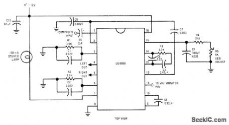
National LM1800 PLL IC accepts composite IF output and converts it to separate audio signals for left and right channels C8 has effect of shunting phase litter to minimize channel separation problems. If free-running frequency of VCO is set at precisely 19kHz with R5, separation remains constant over wide range of composite input levels, signal frequencies, temperature changes, and drift in component values,-“Linear Applications, vol. 2,” National Semiconductor, Santa Clara, CA, 1976, AN-81, p 7-8. (View)
View full Circuit Diagram | Comments | Reading(4127)
TRIODE_VARIABLE_RESISTANCE_THRESHOLD_CONTROL_SWITCH
Published:2009/7/17 9:17:00 Author:Jessie
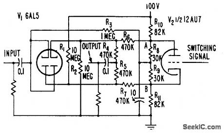
Passes only signals above predetermined positive and negative threshold value, for suppression of audio bockground noise. When V2 is cut off, threshold is at highest value, corresponding to off position of switch. With V2 conducting, threshold will be low and practically all signals appear unclipped at output, corresponding to on position of switch. Provides stable, nontransient switching, independent of changes in tube characteristics.-W. E. Earle, A-C Threshold Converts to Switch, Electronics, 31:1, p 96-99. (View)
View full Circuit Diagram | Comments | Reading(728)
12_14_V_AT_3_A
Published:2009/7/17 5:43:00 Author:Jessie
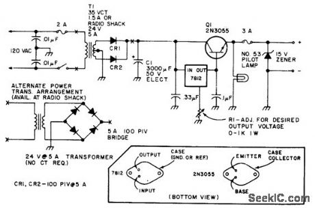
Basic circuit for operating mobile equipment off AC line uses IC voltage regulator in conjunction with series-pass transistor.-Circuits, 73 Magazine, Holiday issue 1976, p 170.
(View)
View full Circuit Diagram | Comments | Reading(2124)
ACTIVE_TONE_CONTROLS_USING_FEEDBACK
Published:2009/7/10 6:15:00 Author:May
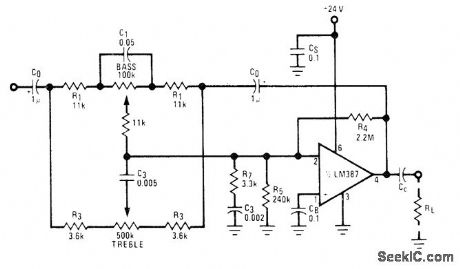
Variation of Baxandall negative-feedback tone control circuit reduces number of capacitors required. Developed for stereo systems. R4 and R5 provide negative input bias for opamp, while C0 prevents DC voltages from being fed back to tone control circuit. For other supply voltages, R4 is only resistor changed; design procedure is given.- Audio Handbook, National Semiconductor, Santa Clara, CA, 1977, p 2-40-2-49. (View)
View full Circuit Diagram | Comments | Reading(3826)
5_V_WITH_DOUBLER
Published:2009/7/17 5:42:00 Author:Jessie
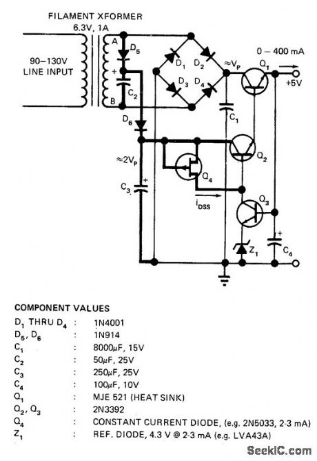
Doubling permits use of inexpensive 6.3-V filament transformer without risking loss of regulation when line voltage drops below about 105 V. With values shown, output varied only 6 mV for line voltage range of 95 to 135 V. Doubler circuit consists of C2, C3, D1, D3, D5, and D6.-A. Paterson, Voltage Doubler Prevents Supply from Losing Regulation, EDN Magazine, Nov. 1, 1972, p 46. (View)
View full Circuit Diagram | Comments | Reading(891)
_138_VDC_AT_18_A
Published:2009/7/17 5:36:00 Author:Jessie
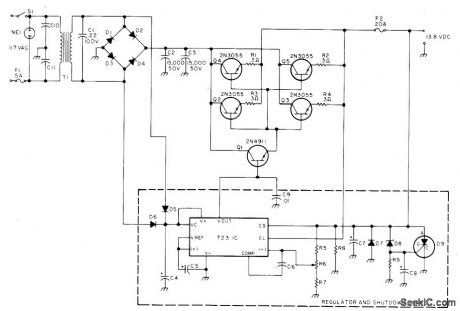
Developed for use with amateur radio transceiver. Transformer secondary is rated 25 VAC at 12 A. When output voltage exceeds 15 VDC, zener D8 (1N965A or equivalent) conducts and fires 2N4441 SCR to crowbar supply and protect transceiver Parts values are: R5 1.8 K, R6 2.5 K, R7 2.7 K, R8 1.5 K, R9 1 K, C4 250 Μf, C5-C6 1.2 μF, C7 220 μF, C8 100 μF, C9-C11 0.01 Pf, D1-D4 1N3492 or equivalent with 100 PIY at 18 A, D5-D6 1N4607 or equivalent, and D7 1N4002 or equivalent.-T. Lawrence, Build a Brute Power Supply, 73 Magazine, Aug. 1977, p 78-79. (View)
View full Circuit Diagram | Comments | Reading(2421)
REVERBERATION_ENHANCEMENT
Published:2009/7/10 6:14:00 Author:May
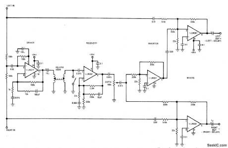
Can be used to synthesize stereo effect from monaural source or can be added to existing stereo sys-tem. Requires only one spring assembly, which can be Accutronics 4BB2CIA. All opamps are National LM387 low-noise dual units. Outputs are inverted scaled sums of original and delayed signals; left output is left signal minus delay, while right output is right signal plus delay. With mono source, both inputs are tied together and outputs become input minus delay and input plus delay.- Audio Handbook, National Semiconductor, Santa Clara, GA, 1977, p 5-7-5-10. (View)
View full Circuit Diagram | Comments | Reading(842)
5_V_FROM_AC_OR_DC
Published:2009/7/17 5:33:00 Author:Jessie
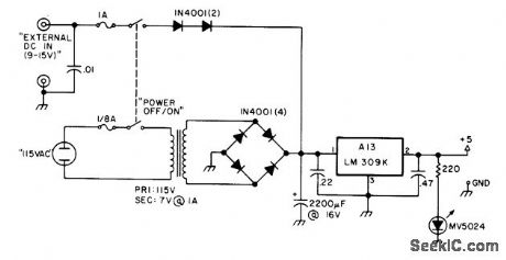
Developed for use with secondary frequency standard to permit checking frequency of amateur radio transmitter at station or in field. Any battery capable of delivering 250 mA at 9-15 V is suitable.-T. Shankland, Build a Super Standard, 73 Magazine, Oct. 1976, p 66-69. (View)
View full Circuit Diagram | Comments | Reading(754)
| Pages:809/2234 At 20801802803804805806807808809810811812813814815816817818819820Under 20 |
Circuit Categories
power supply circuit
Amplifier Circuit
Basic Circuit
LED and Light Circuit
Sensor Circuit
Signal Processing
Electrical Equipment Circuit
Control Circuit
Remote Control Circuit
A/D-D/A Converter Circuit
Audio Circuit
Measuring and Test Circuit
Communication Circuit
Computer-Related Circuit
555 Circuit
Automotive Circuit
Repairing Circuit