
Circuit Diagram
Index 818
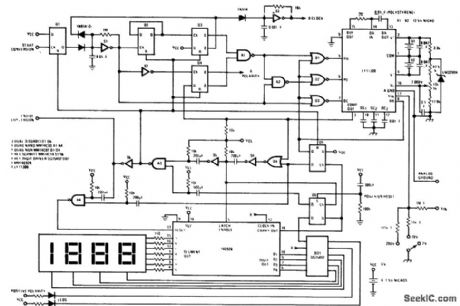
Five_digit_accumulator_elapsed_time_and_indicator
Published:2009/7/19 20:56:00 Author:Jessie
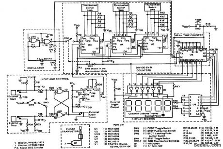
Five-digit accumulator/elapsed time and indicator. The elapsed time indicator has a maximum event of 9999.9 seconds. The accumulator has a maximum count of 99.999 times N, where N is a prescaler number from 1 to 999 (courtesy Motorola Semiconductor Products Inc.). (View)
View full Circuit Diagram | Comments | Reading(1767)
N+1WIRES_CONNECT_N_HALL_EFFECT_SWITCHES
Published:2009/7/10 5:03:00 Author:May
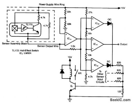
Hall-effect switches have several advantages over mechanically and optically coupled switches. Their major drawback is that they require three wires per device. This circuit, however, reduces this wire count to N + 1 wires for N devices.Amplifter IC1A is configured as a current-to-voltage converter. It senses the sensor assembly's output current. When the Hall-effect switch is actuated, the sensor's output current increases to twice its quiescent value. Amplifter IC1B, conftgured as a comparator, detects this increase. The comparator's output goes low when the Hall-effect switch turns on.The circuit also contains a fault-detection function. If any sensor output wire is open, its corresponding LED will turn on. If the power-supply line opens, several LEDs will tum on. A short circuit will also tum an LED on. Every time an LED tums on, Q1 turns on and the alarm relay is actuated.
(View)
View full Circuit Diagram | Comments | Reading(717)
PULSED_X_BAND_MAGNETRON
Published:2009/7/19 20:54:00 Author:Jessie
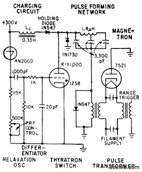
Differentiator forms sharp 2-microsec pulse at trailing each of each sawtooth waveform generated by R-C charging circuit and Shockley pnpn diode. Pulse triggers thyratronto discharge pulse-forming network, and new pulse is stepped up to 4,500 v by pulse transformer for magnetron.-J. Scott, D. Randise, and R. P. Lukacovic, Portable Radar Traces Battlefield Deployment, Electronics, 33:12, p 67-70. (View)
View full Circuit Diagram | Comments | Reading(2062)
31_2_digit_autoranging_multimeter_using_an_MC14433
Published:2009/7/19 20:54:00 Author:Jessie
31/2-digit autoranging multimeter using an MC14433. The multimeter includes ranges from 200 millivolts 200 volts, AC and DC ampere ranaes from 2 milliamperes to 2 amperes full scale and resistance ranges from 2k to 2M full scale(courtesy Motorola semiconductor Products Inc.). (View)
View full Circuit Diagram | Comments | Reading(4299)
BATTERY_TRIGGERED_ac_SWITCH
Published:2009/7/10 5:02:00 Author:May
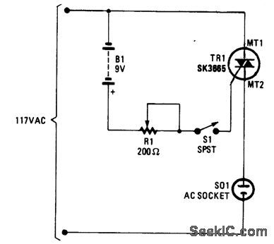
Using this method, a small switch (S1) can con-trol a large ac load. R1 is adjusted for reliable trig-gering and should be as large as possible. (View)
View full Circuit Diagram | Comments | Reading(674)
DOUBLE_PULSE_GENERATOR
Published:2009/7/19 20:52:00 Author:Jessie
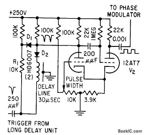
Used in responder-interrogator range computer to produce pair of 15-microsec-wide pulses spaced 30 microsec. Monostable mvbr receives two triggers, one through 30-microsec delay line, and produces 15-microsec pulse for each trigger received.-H. Vantine, Jr., and E.C. Johnson, Modified Transceivers Compute Distance, Electronics, 31:37, p 94-98. (View)
View full Circuit Diagram | Comments | Reading(771)
445_KC_TUNNEL_DIODE_AMPLIFIER
Published:2009/7/10 5:02:00 Author:May
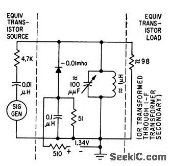
Has approximately 20 db gain.-I. A. Lesk, N. Ho-Ionyak, Jr, and u. s. Dovidsohn, The Tunnel Diode-Circuits and Applicalions, Electronics,32:48,p 60-64. (View)
View full Circuit Diagram | Comments | Reading(738)
2_1_2_diigit_DVM_using_a_binary_D_A_convener_to_accomplish_conversion_of_the_BCD_input_signal
Published:2009/7/19 20:51:00 Author:Jessie
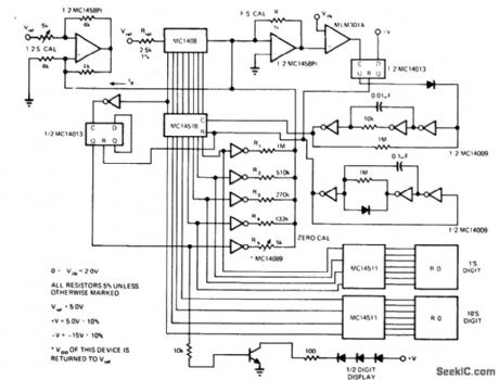
21/2-diigit DVM using a binary D/A convener to accomplish conversion of the BCD input signal (courtesy Motorola Semiconductor Products Inc.). (View)
View full Circuit Diagram | Comments | Reading(780)
DIVIDE_BY_2_OR_3_CIRCUIT
Published:2009/7/10 5:01:00 Author:May
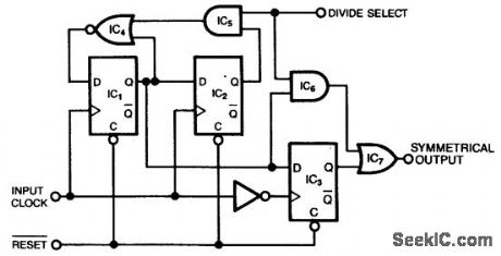
This circuit produces a symmetrical waveform when dividing by either 2 or 3. The Divide Select input controls the division factor. When Divide Select is high, flip-flops IC1 and IC2, along with associated gates, form the classical divide-by-3 circuit.
When divide select is low, however, the output of the AND gate, IC5, goes low. Consequently, the NOR gate, IC4, inverts the feedback signal and passes it to the D input of the flip-flop, IC1. Now, IC1 acts like a toggle flip-flop and produces a divide-by-2 output.
IC3, which is, in effect, a negative-edge-triggered flip-flop, provides symmetrical output signals. When you select division by 2 (Divide Select is low), the output and AND gate IC6 is low, and IC3 simply clocks out the divider's output, delayed by one clock period. When you set Divide Select high, the path to the output through the AND and OR gates, IC6 and IC7, is enabled. This path means that the output goes high on the leading edge of IC3's input (not its output) and produces a symmetrical divide-by-3 output. (View)
View full Circuit Diagram | Comments | Reading(1244)
KLYSTRON_SERVO
Published:2009/7/19 20:51:00 Author:Jessie

Simple three-tube modecentering servo is only control required for local-oscillator klystron in wide-band receiver of short-pulse radar system.-C. D. Hardin and J. Salerno, Miniature X-Band Radar Has High Resolution, Electronics, 32:5, p 48-51. (View)
View full Circuit Diagram | Comments | Reading(774)
7490÷N_CIRCUITS
Published:2009/7/10 5:01:00 Author:May
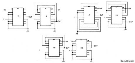
A 7490, 74LS90, 74C90, etc., is a decode divider, but it can be configured to divide by any N up to 10. The above figures illustrate the connections necessary to divide by N from 5 to 10. (View)
View full Circuit Diagram | Comments | Reading(3554)
_5V_AT_3A
Published:2009/7/19 20:50:00 Author:Jessie
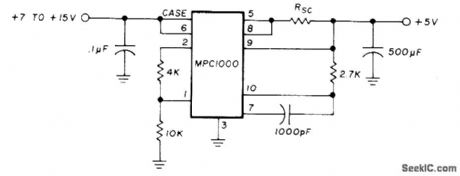
Uses Motorola MPC1000 positive voltage regulator to provide high current required for large TTL project. Current-limiting resistor RSC is in range of 0.66 to 0.066 ohm. Use copper wire about 50% longer than calculated length and shorten step by step until required pass current is obtained; thus, start with 25 ft of No. 16, 15 ft of No. 18, 10ft of No. 20, or 6 ft of No. 22.-G. L. Tater, The MPC1000-Super Regulator, Ham Radio, Sept. 1976, p 52-54. (View)
View full Circuit Diagram | Comments | Reading(766)
12_37V_AT_15A
Published:2009/7/19 20:49:00 Author:Jessie
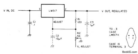
Uses National LM317 adjustable three-terminal positive voltage regulator. Output voltage is determined by ratio of R1 and R2. Output can be adjusted from 37 V down to 1.2V with R2. If DC input is 40V, regulation is about 0.1% at all settings when going from no load to full load. Regulator includes overload and thermal protection. If current limit is exceeded, regulator shuts down. C2 and C3 are optional; C2 improves ripple rejection, and ca prevents instability when load capacitance is between 500 and 5000 pF.-Adjustable Bench Supply, 73Magazine, Dec. 1977, p 192-193 (View)
View full Circuit Diagram | Comments | Reading(1059)
65_CPS_AMPLIFIER
Published:2009/7/10 5:01:00 Author:May
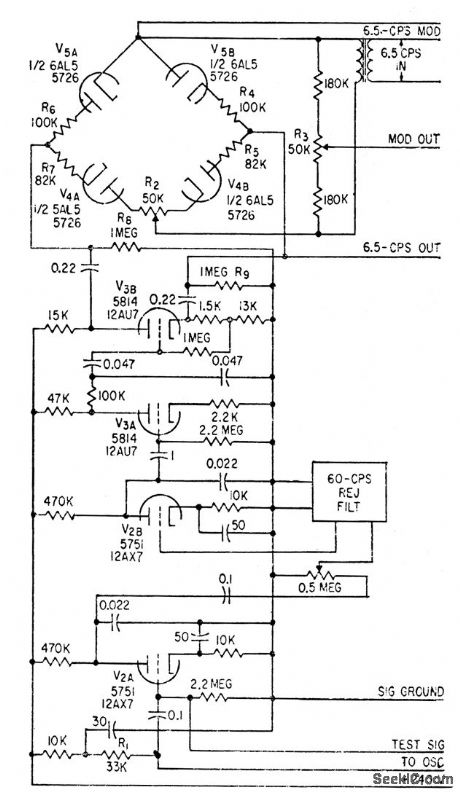
Consists of three triode stages (V2A, V2B, and V3A). Peaks at about 6.5 cps, with 18 db attenuation at each octave. Double-T reiection filter between V2A and V2B ottenuates any 60-cps pickup. Overall gain is 80 db. Phase inverter V3B provides 180° out-of-phase signal for full-wave phose-sensitive bridge rectifier that uses reference signal.Output is rectified error signal for infrared analyzer used to detect leaks in automobile air-suspension systems.-P. G.Balko, Infrared Finds Auto Suspension Leaks, Electtonics, 31:49, p 82-85. (View)
View full Circuit Diagram | Comments | Reading(667)
Dual_polarity_3_1_2_digit_voltmeter
Published:2009/7/19 20:49:00 Author:Jessie
Dual-polarity 31/2-digit voltmeter. The complete circuit of nine packages and external components can be built on a 3- by 5-inch circuit board (coudesy National Semiconductor Corporation). (View)
View full Circuit Diagram | Comments | Reading(909)
BEEPER
Published:2009/7/10 5:00:00 Author:May
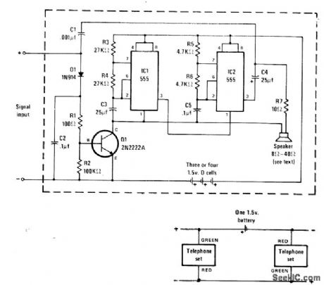
Private two-station telephone system for home requires only two wires between ordinary telephone sets, with 1.5-V battery in series with one line, but this voltage is not enough to actuate ringers in sets.Beeper in parallel with each set, with polarity as shown, serves same purpose as ringer. 555 timer IC1 turns on IC2 about once every 3 s, and IC2 then generates 1000-Hz beep for about 1 s as ringing signal. No switches are required, because telephone handsets provide automatic switching.When both telephones are hung up, 1.5-V battery splits equally between beepers and resulting 0.75 V is not enough to turn on Q1 in either set. When one telephone is picked up, beeper at other telephone receives close to 1.5 V and Q1 turns on IC1 to initiate beeping call. When other telephone is picked up, beeping automatically stops because 1.5 V is again divided between sets.-P. Stark, Private Telephone: Simple Two-Station Intercom, Modern Electronic, July 1978, p 32-34. (View)
View full Circuit Diagram | Comments | Reading(0)
Five_in_one_op_amp_specs_test_circuit
Published:2009/7/19 20:47:00 Author:Jessie
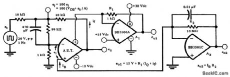
Five-in-one op amp specs test circuit. Tests can be made for open-loop gain, offset voltage, input bias current, quiescent current and output voltage swing (courtesy Burr-Brown Research Corporation). (View)
View full Circuit Diagram | Comments | Reading(714)
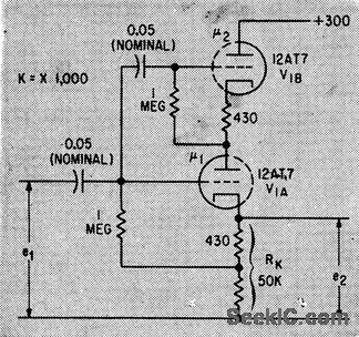
ISOLATION_AMPLIFIER_1
Published:2009/7/10 4:59:00 Author:May
Effective gain stability factor is approximately equal to reciprocal of product of omplification factors of two halves of tube. Gives high transmission accuracy, with high input impedance.-G. M. Davidson and R. F. Brady, Unity-Gain Ampliler Offers High Stcability, Electronics, 33:9, p 66-67. (View)
View full Circuit Diagram | Comments | Reading(795)
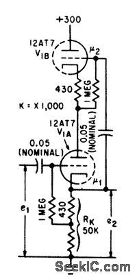
ISOLATION_AMPLIFIER
Published:2009/7/10 4:58:00 Author:May
Gain stability and input impedance are much better than conventional cathode follower. Feedback capacitor goes between triode grids, but may also go between grid of V1B and cathode of V1A.-G. M. Davidson and R. F. Brady, Unity-Gain Amplifier Offers High Stability, Electronics, 33:9, p 66-67. (View)
View full Circuit Diagram | Comments | Reading(999)
SOLAR_CELL_AMPLIFIER
Published:2009/7/10 4:57:00 Author:May
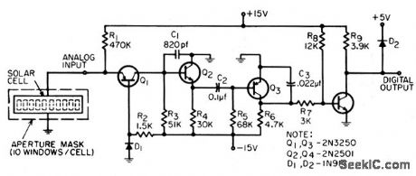
Used with mulliaperture solar cells to genorate 10 strobe pulses.Eight circuits with cells one needed to generate 80 strobe pulses for reading conventional punched card.-C. R. Hearn,Multi-Aperture Solar Cell Amplifiter,EEE,14:4,p 43-44. (View)
View full Circuit Diagram | Comments | Reading(914)
| Pages:818/2234 At 20801802803804805806807808809810811812813814815816817818819820Under 20 |
Circuit Categories
power supply circuit
Amplifier Circuit
Basic Circuit
LED and Light Circuit
Sensor Circuit
Signal Processing
Electrical Equipment Circuit
Control Circuit
Remote Control Circuit
A/D-D/A Converter Circuit
Audio Circuit
Measuring and Test Circuit
Communication Circuit
Computer-Related Circuit
555 Circuit
Automotive Circuit
Repairing Circuit