
Circuit Diagram
Index 811
TEMPERATURE_COMPENSATION_IN_EGG_AMP
Published:2009/7/17 5:22:00 Author:Jessie

Circuit has common-mode rejection ratio of 10,000, with adjustable cancellation of unbalanced noise at input, for electrocardiograph. For temperature compensation, C3 bypasses ac signals from base of Q7, so only d-c signals are fed back through this transistor to Q1.-J. R. Smith, Jr., Amplifier Can be Adjusted to Cancel Unbalanced Noise, Electronics, 37:23, p 60-61. (View)
View full Circuit Diagram | Comments | Reading(676)
256_NEGATIVE_STEPS
Published:2009/7/10 6:01:00 Author:May
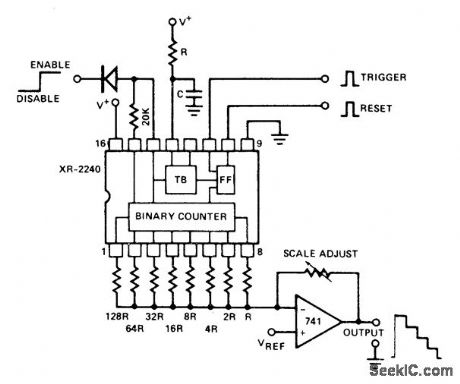
Interconnection of Exar XR-2240 programmable timer/counter with 741 opamp and precision resistor ladder forms staircase generator. Reset pulse drives output low. When trigger is applied, output goes high and circuit generates negative-going staircase having 256 equal steps. Duration of each step is equal to time-base period as determined by values used for R and C. Staircase is stopped by applying disable signal (less than 1.4V) to pin 14 through steering diode. Supply voltage range is 4-15 V. If counter cannot be triggered when using supply above 7 V and less than 0.1μF for C, connect 300 pF from pin 14 to ground.- Timer Data Book, Exar Integrated Systems, Sunnyvale, GA, 1978, p 11-18. (View)
View full Circuit Diagram | Comments | Reading(2441)
Voltage_controlled_low_pass_filter
Published:2009/7/17 5:22:00 Author:Jessie
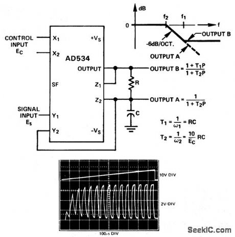
Voltage-controlled low-pass filter. The oscilloscope photo shows the circuit's response to a square wave with a ramp input. As an example if R is 8 K and C is 0.002 μF output A has a pole' frequency from 100 Hz to 10 kHz for Ea ranging from 100 mV to 10 V. Output B has an additional zero at 10 kHz. The circuit can be converted to a high-pass filter by interchanging C and R (courtesy Analog Devices, Inc.). (View)
View full Circuit Diagram | Comments | Reading(0)
PULSE_TRAINS_FORM_STAIRCASE
Published:2009/7/10 5:59:00 Author:May
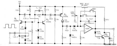
Circuit accepts pulse trains from pulse-generating position transducer and produces staircase wave-form as analog input for horizontal axis of XY recorder or storage scope. Current-regulating diode serves as constant-current source for staircase generator that produces analog out-put proportional to number of input pulses. Mono switches on Q3 for constant time duration with every pulse, to ensure that C5 gets same amount of charge regardless of pulse rate. Relay resets integrator to zero when output voltage reaches almost 8.7 V, to prevent data from being lost if opamp saturates before data run is completed.-R. G. Warsinski, Staircase Generator Uses Current-Regulating Diode, EDN|EEE Magazine, Aug. 1, 1971, p 46. (View)
View full Circuit Diagram | Comments | Reading(1352)
PULSED_DISTRIBUTED_AMPLIFIER
Published:2009/7/17 5:21:00 Author:Jessie
Gives 20% bandwidth centered on 200 Mc. Used as output stage of moderate-power radar, final drive of high-power drive, and for high-level pulse amplification.-S. K. Meads, How to Design Pulsed Distributed Amplifiers, Electronics, 32:12, p 56-58. (View)
View full Circuit Diagram | Comments | Reading(1073)
Digitally_programmable_low_pass_filter
Published:2009/7/17 5:20:00 Author:Jessie
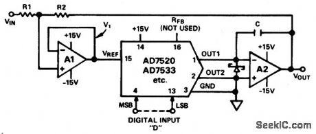
Digitally programmable low-pass filter. The two op amps are a AD747 (courtesy Analog Devices, Inc.). (View)
View full Circuit Diagram | Comments | Reading(805)
STEP_FU_NCTION_GENERATOR
Published:2009/7/10 5:57:00 Author:May
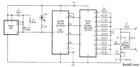
Successively lower resistances at decoder outputs create stairstep function for testing various types of instruments. Steps are equally spaced and of equal height, covering range of 5-12 or 50-120 mV depending on setting of range switch and RS. Spacing between steps ranges from 1.6 s to 6 min, so total time for complete 10-step stair-case is 16 s to 60 min depending on setting of 2.5-megohm timer pot. Reference voltage Vb can be 1.45-V mercury cell. Resistor values shown for Rd provide fixed 10% increments in stairstep.-M. M. Lacefield, Simple Step-Function Generator Aids in Testing Instruments, Electronics, Dec. 26, 1974, p 103 and 105. (View)
View full Circuit Diagram | Comments | Reading(998)
VARIABLE_TIME_INTERVAL_STANDARD
Published:2009/7/17 5:19:00 Author:Jessie
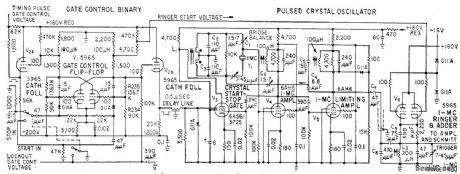
Produces two delayed pulses for establishing accurate time intervals from 1 to 10,000 microsec. Delays are adjustable in 1.microsec increments, with continuous interpolation between steps. Crystal-controlled oscillator and fast preset counters reduce time-delay errors. Useful in calibrating radar and loran timing circuits, oscilloscopes, and marker generators, as well as for precision pulse code modulation and for cadibrating delay lines.-D. Broderick, D. Hartke, and M. Willrodt, Precision Generator for Radar Range Calibrcation, Electronics, 32:14; p 58-60. (View)
View full Circuit Diagram | Comments | Reading(819)
Derivative_controlled_low_pass_filter
Published:2009/7/17 5:19:00 Author:Jessie
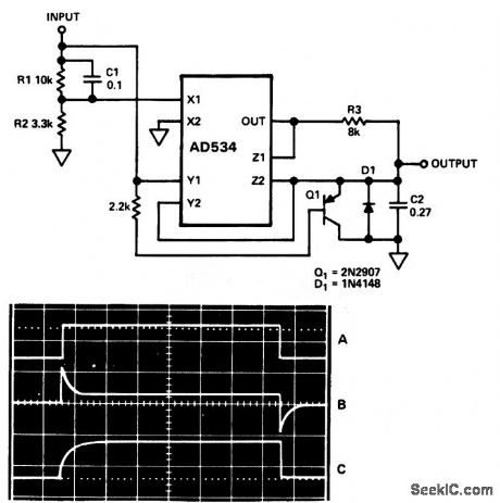
Derivative-controlled low-pass filter. This circuit settles rapidly in response to step changes, then assumes a long time constant for filtering noise. In the oscilloscope photo trace A is the input step, trace B is the control input and trace C is the signal output (courtesy Analog Devices, Inc.). (View)
View full Circuit Diagram | Comments | Reading(603)
SQUARE_TO_STEP
Published:2009/7/10 5:56:00 Author:May
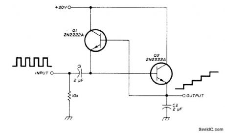
Simple staircase generator circuit converts square wave into staircase voltage output. Each step approximates level of input pulse. First pulse charges C2 to amplitude of input pulse. After pulse, voltage across C2 acts through on to charge Q1 to same voltage. Next pulse adds to voltage across C2, doubling its charge. Each subsequent pulse steps up height of staircase until it reaches level of supply voltage.-J. Fisk, Circuits and Techniques, Ham Radio, June 1976, p 48-52. (View)
View full Circuit Diagram | Comments | Reading(5570)
BLOOD_VOLUME_SERVO
Published:2009/7/17 5:19:00 Author:Jessie
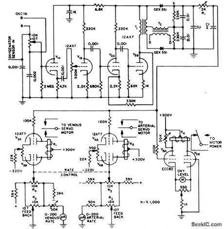
Servo-controlled pump with variable stroke drives blood from venous system of patient into artificial lung and after oxygenation returns it to arterial system. Control circuit insures that volume of blood is constant. Sensor is brass disk forming capacitance with pool of blood in oxygenator at spacing of 1mm. Error signal derived +tom capacitance change unbalances bridge that is energized at 3 kc (points B-B).Amplified error signal is applied to phase-sensitive demodulator. Unbalance energizes center-stable relays K1 and K2 of arterial and venous servo motors, so stroke output of arterial pump is decreased while that of venous pump is increased, or vice versa, to restore preselected volume of blood.-R. Schild and N. Wesson, Servo Circuit Controls Artificial Heart, Electronics, 31:15, p 73-75. (View)
View full Circuit Diagram | Comments | Reading(1068)
STEP_GENERATOR
Published:2009/7/10 5:55:00 Author:May
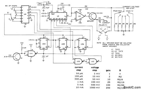
Base-step generator produces series of voltage or current steps synchronized with beginning of each collector voltage sweep, for application to base or gate of three-terminal semiconductor, device while sweep voltage is applied to collector of curve tracer that displays current-voltage characteristics on CRO. Circuit is bulk around Motorola MC1406L 6-bit D/A converter U5. U1 (7400), U2, and U3 (both 7473) form synchronous divide-by-8 counter whose outputs are applied to A1-A3 inputs of US. U6 (MC1741P1) and Q2 form current amplifier. al is general-purpose NPN transistor having DC current gain of about 30. Point A goes to output of full-wave rectifier using two 50-PIV 1-A diodes connected across 26.4-V secondary of transformer. Table gives values for R3 through R8 as ratio of R2 for various gains and steps. Thus, for 500-mV steps (gain of 100), R7 is about 101 ohms. Accuracy depends on values of R2-R9 used. Never apply voltage steps to base of bipolar transistor.-H. Wurzburg, Integrated Circuit Base-Step Generator, Ham Radio, July 1976, p 44-46. (View)
View full Circuit Diagram | Comments | Reading(4554)
HARD_TUBE_MODULATOR
Published:2009/7/17 5:18:00 Author:Jessie
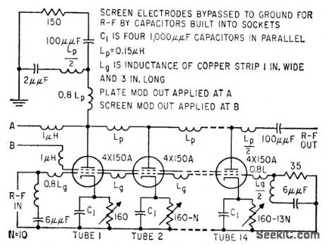
Supplies 0.02-microsec 180-kw modulating pulses at prf of 14,400 pps. Hard tube is used because hydrogen thyratron of adequate power-handling capability would not deionize rapidly enough at this prf.-R. F. P. Smith, Airport Radar Has High Resolution, Electronics, 32:14, p 64-69. (View)
View full Circuit Diagram | Comments | Reading(948)
NEGATIVE_TRIGGERING
Published:2009/7/10 5:54:00 Author:May
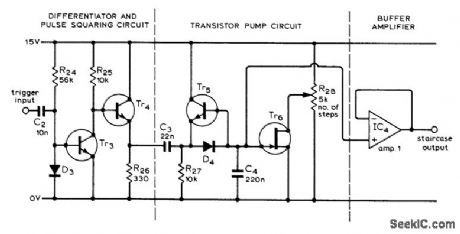
Standard transistor pump circuit is driven by differentiating and squaring circuit designed so each staircase block is triggered by negative edge rather than by pulse. Circuit was developed for FET curve tracer, and can be used in other applications where only resetting edge of normal sawtooth is available as trigger. R28 changes number of steps produced before staircase is reset. Tr6 is Texas Instruments 43, IC opamp is SN72741P, transistors are BC182L or equivalent, and diodes are 1S44.-L. G. Cuthbert, An F.E.T. Curve Tracer, Wireless World, April 1974, p 101-103. (View)
View full Circuit Diagram | Comments | Reading(1132)
Light_operated_6_kV_series_switch_for_high_voltage_crowbar_circuits_or_high_voltage_pulse_forming_networks
Published:2009/7/17 5:17:00 Author:Jessie
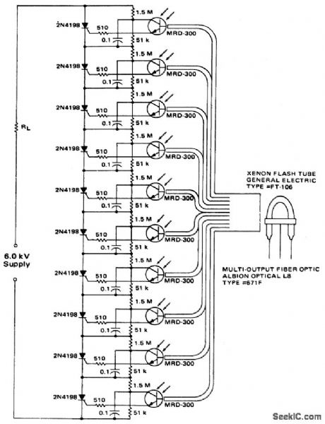
Light-operated 6 kV series switch for high-voltage crowbar circuits or high-voltage pulse-forming networks(courtesy Motorola Semiconductor Products Inc.). (View)
View full Circuit Diagram | Comments | Reading(706)
SEVEN_STEPS
Published:2009/7/10 5:53:00 Author:May
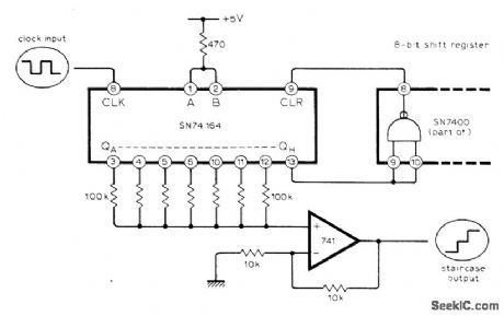
Circuit shown generates seven identical steps before waveform is repeated. Number of steps can be increased by cascading two or more SN74164 shift registers, or reduced by taking dear pulse from earlier a output of register.-P. Cochrane, Simple Staircase Generator, Wireless World, April 1976, p 63. (View)
View full Circuit Diagram | Comments | Reading(1395)
COUNTER_TYPE_CO_NVERTER
Published:2009/7/10 5:52:00 Author:May
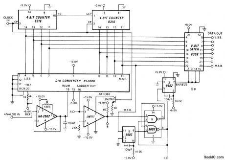
Clock-driven counter drives Harris HI-1080 D/A converter producing staircase voltage ramp. When converter output voltage equals analog input voltage as determined by HA-2602 comparator, comparator changes state. At that instant, state of counter represents 8-bit digital equivalent of analog input. Data output from latch is complement of digital value. Input range is 0-10 V. Other input ranges, positive or negative, are obtained by changing opamp gain or polarity or by adjusting 1K reference pot. Accuracy is maintained within 1/2 LSB at clock rates up to 330 kHz.- Linear & Data Acquisition Products, Harris Semiconductor, Melbourne, FL, Vo1, 1, 1977, p 7-33-7-35 (Application Note 512). (View)
View full Circuit Diagram | Comments | Reading(1054)
4_400_Hz_BIPOLAR
Published:2009/7/10 5:51:00 Author:May
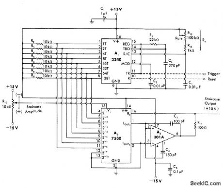
Single 2240 serves as time-base generator with Rt determining frequency in range of 4-400 Hz. Digital output is converted to analog form by 7530 10-bit CMOS multiplying D/A converter. Reference voltage can be varied up to ±10 V to give variable-amplitude bipolar staircase output in same amplitude range, with 255 staircase steps corresponding to 8-bit count of 2240. Opamp A3 serves as current-to-voltage convener for changing ±1 mA output current of 7530 to ±10 V swing for staircase.-W. G. Jung, IC Timer, Cookbook, Howard W. Sams, Indianapolis, IN, 1977, p 224-226. (View)
View full Circuit Diagram | Comments | Reading(717)
48_Hz_12_STEP
Published:2009/7/10 5:50:00 Author:May
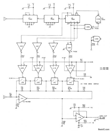
Used to provide 12 shades of gray for reception of satellite facsimile weather pictures. Input 1 is 2400-Hz square wave obtained from separate reference oscillator. Input 2 is 2400-Hz sine wave having 1 V P-P maximum voltage. U9 is 4-bit binary counter having special reset provided by U10A and U10B at count 12 to give desired 12 states. Outputs of U9 are used to adjust gain of U16A in 12 steps. Article describes operation in detail and gives circuits for reference oscillator and power supply.-R. Cawthon, Toward a More Perfect Weather Picture, 73 Magazine, April 1978, p 116-118. (View)
View full Circuit Diagram | Comments | Reading(712)
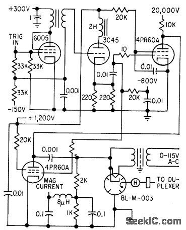
RADAR_PULSER
Published:2009/7/17 5:16:00 Author:Jessie
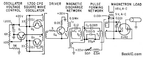
Magnetic discharge and pulse shaping networks are used instead of thyratrons or vacuum-tube amplifiers to re duce size und weight while increasing reliability.-A. Krinitz, Using Magnetic Circuits to Pulse Radar Sets, Electronics, 32:27, p 42-43. (View)
View full Circuit Diagram | Comments | Reading(868)
| Pages:811/2234 At 20801802803804805806807808809810811812813814815816817818819820Under 20 |
Circuit Categories
power supply circuit
Amplifier Circuit
Basic Circuit
LED and Light Circuit
Sensor Circuit
Signal Processing
Electrical Equipment Circuit
Control Circuit
Remote Control Circuit
A/D-D/A Converter Circuit
Audio Circuit
Measuring and Test Circuit
Communication Circuit
Computer-Related Circuit
555 Circuit
Automotive Circuit
Repairing Circuit