
Circuit Diagram
Index 810
12_V_AT_5A
Published:2009/7/17 5:32:00 Author:Jessie
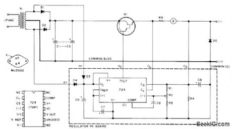
Uses MJ3000 Darlington power device as pass element providing gain of 1000 at 5 A. Output is set to current-limit at 6.5 A. Fuse at X is desirable. Values: R1 is 1.8 K; R2 is 2.5K trimpot; R3 is 2.7K; R4 is 1.5K; R5 is 0.1 ohm at 5 W; C1-C5 are 4000 μF each at 20 V; C6 is 250 μF at 25 V; C7-C8 are1.2 μF at 35 V; C9 is 220 pF; Dl-D2 are MR1120 or equivalent rated 6 A; D3-D4 are 1N4607 or equivalent; D5 is 1N4002 or equivalent; and T1 is 24-28 V CT secondary at 4 A. Article gives design procedure for increasing regulated output to as much as 100 A.-C. Anderton, A Hefty 12 Volt Supply, 73 Magazine. May 1975, p 85-87. (View)
View full Circuit Diagram | Comments | Reading(971)
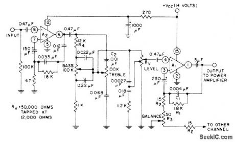
BALANCE_AND_LOUDNESS_CONTROL
Published:2009/7/10 6:13:00 Author:May
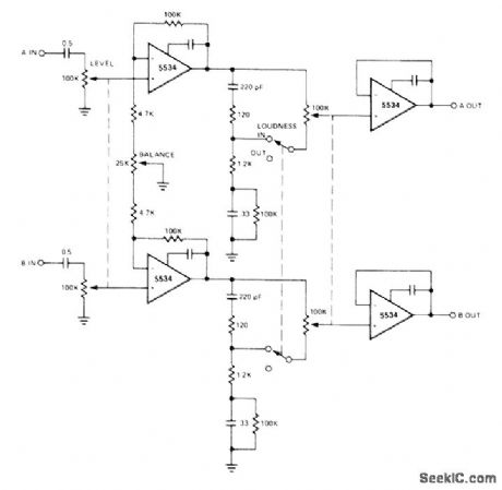
Provides bass boost at low listening levels to compensate for nonlinearity of human hearing sys-tem. Balance control permits equalizing volume from left and right loudspeakers at particular listening location.- Signetics Analog Data Manual, Signetics, Sunnyvale, CA, 1977, p 640. (View)
View full Circuit Diagram | Comments | Reading(1077)
DISTANCE_MARK_GENERATOR_5
Published:2009/7/17 5:29:00 Author:Jessie
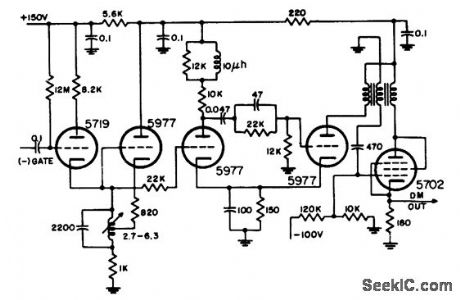
Uses switched Hartley oscillator, mvbr-type trigger shaper, and parallel-triggered blocking oscillator to generate 1.67-mile distance marks in airborne search radar. Blocking-oscillator frequency dividers are used to get 5-and 10-mile marks.-NBS, Handbook Preferred Circuits Navy Aeronautical Electronic Equipment, Vol. 1, Electron Tube Circuits, 1963, p N8-2. (View)
View full Circuit Diagram | Comments | Reading(698)
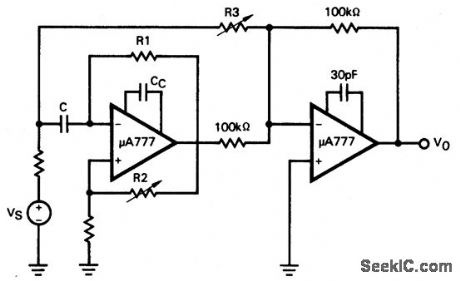
Bandpass_filter_using_a_μA777_op_amp_for_center_frequencies_up_to_50_kHz
Published:2009/7/17 5:26:00 Author:Jessie
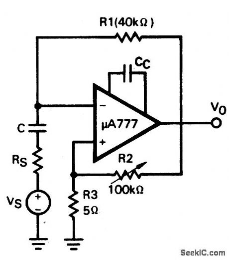
Bandpass filter using a μA777 op amp for center frequencies up to 50 kHz. Set capacitor Cc to 30 pF for frequencies below 10 kHz and 3 pF for frequencies above 10 kHz. Set capacitor C for desired frequency (courtesy Fairchild Semiconductor). (View)
View full Circuit Diagram | Comments | Reading(576)
STEREO_REVERBERATION
Published:2009/7/10 6:12:00 Author:May

Uses National LM377 dual power amplifier as driver for springs acting as mechanical delay lines. Used to enhance performance of stereo music system by adding artificial reverberation to simulate reflection and re-reflection of sound off walls, ceiling, and floor of listening environment. Amplifier has frequency response of 100-5000 Hz, with roll off below 100 Hz to suppress booming. Recovery amplifier uses LM387 low-noise dual preamp, and another LM387 provides mixing of delayed signal with original in inverting summing configuration. Output is about half of original signal added to all of delayed signal.- Audio Handbook, National Semiconductor, Santa Clara, CA, 1977, p 5-7-5-10. (View)
View full Circuit Diagram | Comments | Reading(930)
SUM_AND_DIFFERENCE
Published:2009/7/10 6:11:00 Author:May
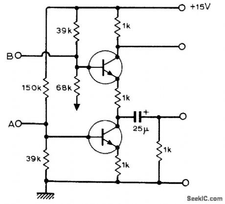
Simple circuit using two BC109 or equivalent transistors is effective for summing and differencing two signals, as required in stereo and quadraphonic sound applications. For resistor values shown, upper output is -1/2(A + B) and lower output is -1/2(A - B). Will handle input signals up to 1.4 V. Bottom of 68K resistor should go to ground.-B. J. Shelley, Active Sum and Difference Circuit, Wireless World, July 1974, p 239. (View)
View full Circuit Diagram | Comments | Reading(1545)
Active_filter_having_a_bandpass_with_60_dB_gain_using_the_ECG925
Published:2009/7/17 5:25:00 Author:Jessie
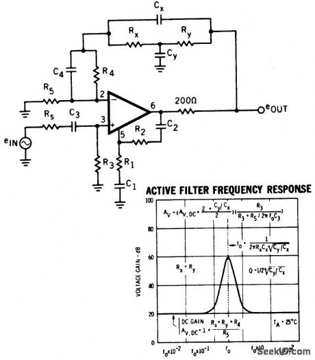
Active filter having a bandpass with 60 dB gain using the ECG925. Typical supply voltage is ±15 volts, but it can be powered with supplies ranging from ±3 volts to ±22 volts. (View)
View full Circuit Diagram | Comments | Reading(813)
ACTIVE_MIDRANGE_TONE_CONTROL
Published:2009/7/10 6:10:00 Author:May
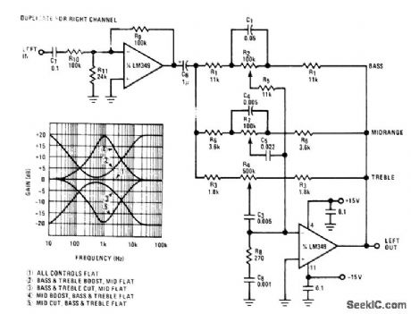
Addition of midrange tone control to active bass and treble control gives greater control flexibility. Center frequency of midrange control is determined by C4 and C5 and is 1 kHz for values shown. C5 should have 5 times value of C4.-“Audio Handbook,” National Semiconductor, Santa Clara, CA, 1977, p 2-40-2-49. (View)
View full Circuit Diagram | Comments | Reading(2194)
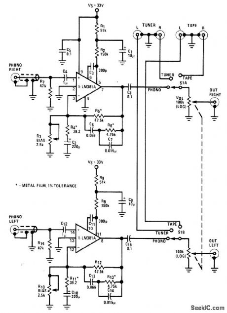
PREAMP_WITH_TONE_CONTROLS
Published:2009/7/10 6:08:00 Author:May
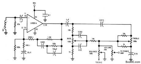
Use of LM381A selected low-noise preamp with passive bass and treble tone controls as phono or tape preamp gives superior noise performance while eliminating need for transistor to off set signal loss in passive controls Circuit provides 20-dB boost and cut at 50 Hz and 10 kHz relative to midband gain, Design equations are given. Use log pots for tone controls. Other stereo channel is identical. Controls are ganged.- Audio Handbook, National Semiconductor, Santa Clara, CA, 1977, p 2-40-2-49. (View)
View full Circuit Diagram | Comments | Reading(2826)
X_RAY_TUBE_PULSER
Published:2009/7/17 5:24:00 Author:Jessie
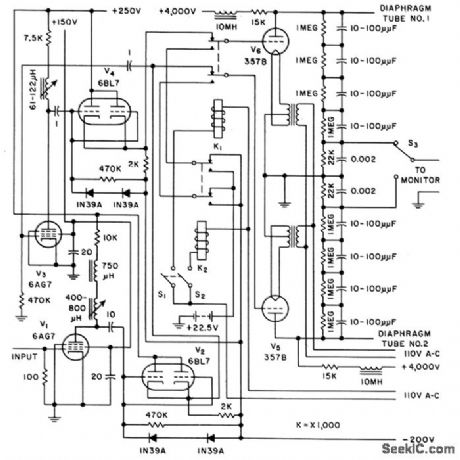
Supplies 3,600 v peakto-peak pulses, swinging from 400 to 4,000 V. Input signal comes from square-wave generator having adjustable duty cycle of 10 to 90% from 35 to 100,000 cps. Uses two pulsating x-ray tubes, each controlled by applying low-voltage square-wave to special diaphragm element. Anode current is maintained constant by switching alternately be. tween tubes. Used for delivering therapeutic dose levels.-E. F. Weller, Roof-Top Target Tubes Pulse X-Rays, Electronics, 31:11,p 138-139. (View)
View full Circuit Diagram | Comments | Reading(2782)
53_dB_PREAMP
Published:2009/7/10 6:07:00 Author:May
RCA CA3052 quad AC amplifier serves for both channels of complete stereo preamp. Circuit is duplicated for other channel. Total harmonic distortion at 1-kHz reference and 1-V output is less than 0.3%. Gain at 1 kHz is 47 dB, with 11.5-dB boost at 100 Hz and 10 kHz. Cut at 100 Hz is 10 dB and at 10 kHz is 9 dB. Operates from single-ended supply. Inputs can be from tape recorders and magnetic-cartridge phonographs.- Lin ea r Integrated Circuits and MOS/FET's, RCA Solid State Division, Somerville, NJ, 1977, p 327-330. (View)
View full Circuit Diagram | Comments | Reading(1125)
STEREO_FM_DEMODULATOR
Published:2009/7/10 6:07:00 Author:May
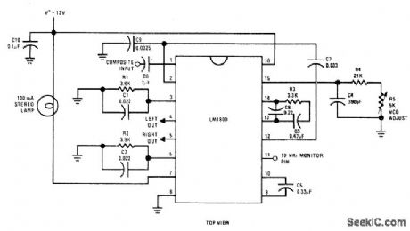
Single National LM1800 IC converts composite AF input signal to left and right signals for audio power amplifiers LED with series resistor can be used in place of 100-mA lamp.-“Audio Handbook,” National Semiconductor, Santa Clara, CA, 1977, p 3-23-3-27. (View)
View full Circuit Diagram | Comments | Reading(910)
ULTRALOW_NOISE_PREAMP
Published:2009/7/10 6:06:00 Author:May
Complete preamp has inputs for magnetic-cartridge pickup, tuner, and tape, along with ganged volume control and ganged selector switch for both channels. Tone controls are easily added. RIAA frequency response is within ±0.6 dB of standard values. 0-dB reference gain at 1 kHz is 41.6 dB, producing 1.5-VRMS output from 12.5-mVRMS input. Signal-to-noise ratio is better than -85 dB referenced to 10-mV input level- Audio Handbook, National Semiconductor, Santa Clara, CA, 1977, p 2-25-2-31. (View)
View full Circuit Diagram | Comments | Reading(0)
1_MHz_bandpass_filter_insertion_loss_tester
Published:2009/7/17 5:24:00 Author:Jessie
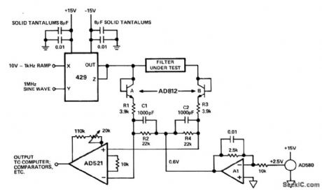
1 MHz bandpass filter insertion-loss tester. The test is performed by sweeping the amplitude of the input signal and comparing the envelopes of the input and output signals, The test signal is produced by modulating a 1 MHz sinusoidal carrier with a 10-volt 1 kHz ramp using a 429 multiplier. The test signal is demodulated by the diode-connected AD812A and network R1-R2-C1.The signal coming out of the filter under test is passed through an identical network consisting of AD812B, R3, R4 and C2. The AD521 compares the two demodulated outputs (courtesy Analog Devices, Inc.). (View)
View full Circuit Diagram | Comments | Reading(1027)
REAR_CHANNEL_AMBIENCE
Published:2009/7/10 6:05:00 Author:May
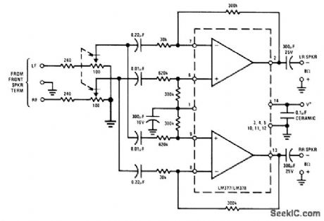
Can be added to existing left front and right front loudspeakers of stereo system to extract difference signal for combining with some direct signal (R or L) to add fullness for concert-hall realism during re-production of recorded music. Very little power is required for pair of rear loudspeakers, and this can be furnished by National LM377/LM378 dual-amplifier IC operating from about 24-V supply.- Audio Handbook, National Semi-conductor, Santa Clara, CA, 1977, p 4-8-4-20. (View)
View full Circuit Diagram | Comments | Reading(811)
FM_NOISE_SUPPRESSOR
Published:2009/7/10 6:04:00 Author:May
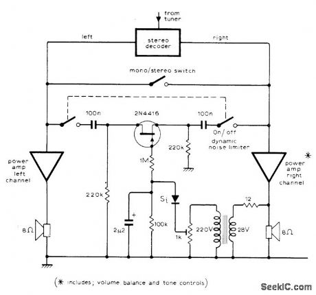
Circuit acts as noise limiter to help produce pseudostereo sound having reduced noise, to offset noise signal heard during weak passages during stereo reception of FM stations. FET short-circuits both audio channels when audio signal strength drops sufficiently to make noise objectionable. H this voltage is insufficient to drive FET, amplifier or transformer must be used.-J. W. Richter, Stereo Dynamic Noise Limiter, Wire-less World, Oct, 1975, p 474. (View)
View full Circuit Diagram | Comments | Reading(1040)
BLOCKING_OSCILLATOR_MODULATOR
Published:2009/7/17 5:24:00 Author:Jessie
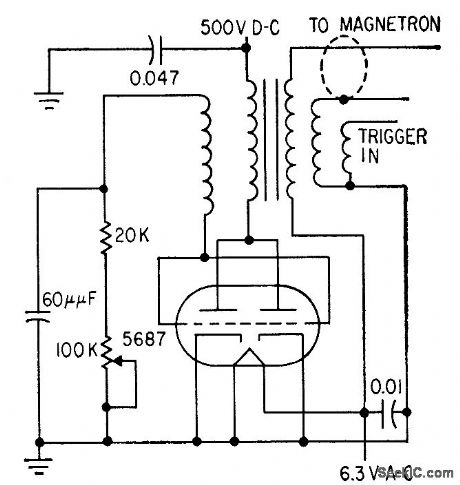
High permeability of ferrite-core transformer allows use of few coil turns, keeping capacitance at minimum so narrow pulses are produced.-C. D. Hardin and J. Salerno, Miniature X.-Band Radar Has High Resolution, Electronics, 32:5, p 48-51. (View)
View full Circuit Diagram | Comments | Reading(754)
ACTIVE_TONE_CONTROLS
Published:2009/7/10 6:03:00 Author:May
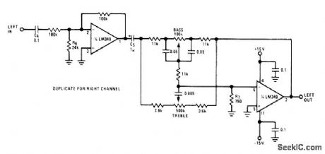
Provides ±20 dB gain with 3-dB corners at 30 and 10,000Hz,Use of LM349 quad opamp means only one IC is needed for both stereo channels, Buffer at input gives high input impedance (100k) for source, Total harmonic distortion is typically 0.05% across audio band Input-to-output gain is at least 5.-“Audio Handbook,” National Semiconductor, Santa Clara, CA, 1977,p 2-40-2-49. (View)
View full Circuit Diagram | Comments | Reading(1123)
GRAY_SCALE_TEST_GENERATOR
Published:2009/7/10 6:01:00 Author:May

Synchronized LO oscillator drives staircase generator, both of which are reset by horizontal-blanking input signal. Developed for testing video equipment. Synchronized oscillator uses two TTL gates of SN5400, biased at their linear range by negative feedback resistors R1 and R2. Oscillator always starts in same condition. Circuit generates staircase by integrating train of equally spaced pulses Article covers theory and gives design equations.-E. E. Morris, Simple Stair-Step Generator Uses 1IC and 3 Transistors, EDN Magazine, Oct. 1, 1972, p 48-49. (View)
View full Circuit Diagram | Comments | Reading(1349)
Notch_filter_for_up_to_50_kHz_using_two_μA777_op_amps
Published:2009/7/17 5:22:00 Author:Jessie
Notch filter for up to 50 kHz using two μA777 op amps (courtesy Fairchild Semiconductor). (View)
View full Circuit Diagram | Comments | Reading(616)
| Pages:810/2234 At 20801802803804805806807808809810811812813814815816817818819820Under 20 |
Circuit Categories
power supply circuit
Amplifier Circuit
Basic Circuit
LED and Light Circuit
Sensor Circuit
Signal Processing
Electrical Equipment Circuit
Control Circuit
Remote Control Circuit
A/D-D/A Converter Circuit
Audio Circuit
Measuring and Test Circuit
Communication Circuit
Computer-Related Circuit
555 Circuit
Automotive Circuit
Repairing Circuit