
Circuit Diagram
Index 815
Automotive_battery_saver
Published:2009/7/17 4:52:00 Author:Jessie
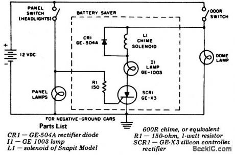
Automotive battery saver. This circuit uses an SCR and doorbell chime. This complete circuit can be built inside the doorbell chime housing. It is only operational when the dome light and panel light are on. The only time this occurs is when the door is open and the parking or head lights are on. Note that the SCR gate is connected to the car's panel lights (courtesy General Electric Company). (View)
View full Circuit Diagram | Comments | Reading(1411)
_5AND__12_V_AT6_mA
Published:2009/7/17 4:51:00 Author:Jessie
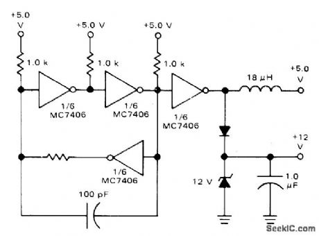
Circuit using four sections of Motorola MC7406 provides +12V supply required by MCM6570 8192-bit character generator using 7×9 matrix, along with conventional +5 V.- A CRT Display System Using NMOS Memories, Motorola, Phoenix, AZ, 1975, AN-706A, p5, (View)
View full Circuit Diagram | Comments | Reading(824)
Audio_dancing_lights_with_three_channels
Published:2009/7/17 4:51:00 Author:Jessie
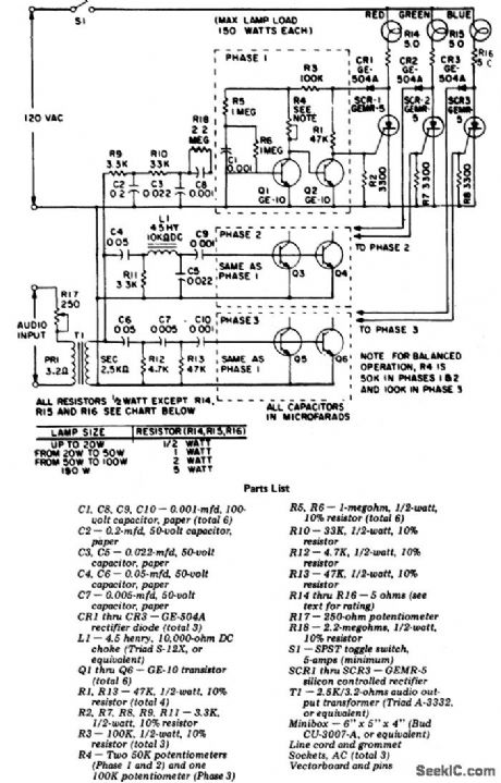
Audio dancing lights with three channels. This circuit uses the audio output from your stereo and separates the high, low and medium frequencies to activate three colored lights. Input sensitivity is controlled by R17 (courtesy General Electric Company). (View)
View full Circuit Diagram | Comments | Reading(1443)
Norton_ac_amplifier_with_±15__V_supplies
Published:2009/7/17 4:51:00 Author:Jessie
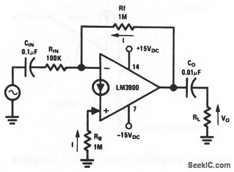
This circuit uses one section of an LM3900 to form an ac-coupled amplifier, where both inputs bias at one VBE above the -VEE voltage (about -15 V). With RF=RB, VO will bias at about 0 V to allow a maximum output swing.Because pin 7 is common to all four amplifiers in the package, the other amplifiers are also biased for operation with ±15-V supplies. National Semiconductor Linear Applications Handbook 1991, p 246 (View)
View full Circuit Diagram | Comments | Reading(667)
Morse_code_set_using_an_LM3909_chip
Published:2009/7/17 4:50:00 Author:Jessie
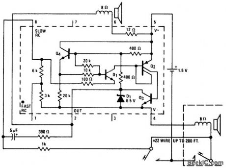
Morse code set using an LM3909 chip. Circuitry inside dashed lines is the LM3909. The three-wire system and parallel telegraph keys allow the user to practice with send/receive switches (courtesy National Semiconductor Corporation). (View)
View full Circuit Diagram | Comments | Reading(797)
Norton_Schmitt_triggers
Published:2009/7/17 4:49:00 Author:Jessie
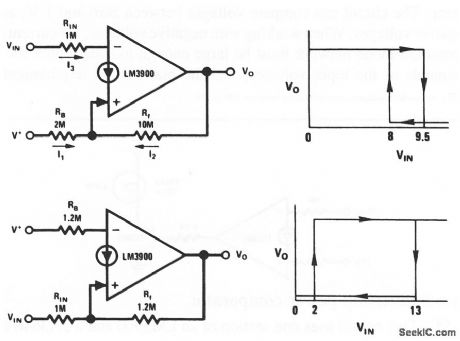
This circuit uses one section of an LM3900 connected to form a Schmitt trigger. Both inverting and noninverting versions are shown. By adjusting the values of RB, RF, and /RIN, the switching values of VIN can be set to any desired levels. National Semiconductor Linear Applications Handbook 1991 p 244 (View)
View full Circuit Diagram | Comments | Reading(777)
Automotive_burglar_alarm_for_12_volt_negative_ground_systems
Published:2009/7/17 4:49:00 Author:Jessie
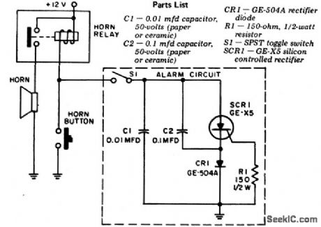
Automotive burglar alarm for 12-volt negative ground systems. The entire alarm circuit (inside dashed lines) can be mounted on the SPST toggle switch. The circuit is triggered whenever any electrical device in the car is turned on. To turn off the alarm it is necessary to turn off S1 or hit the horn button. Mount S1 in the truck (courtesy General Electric Company). (View)
View full Circuit Diagram | Comments | Reading(868)
O1_35V_AT_1A
Published:2009/7/17 4:48:00 Author:Jessie
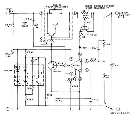
CA3160 serves as error amplifier in continuously adjustable regulator that functions down to vicinity of 0 V. RC network between base of 2N2102 output drive transistor and input source prevents turn-on overshoot. Input regulation is better than 0.01%/V, and regulation from no load to full load is better than 0.005%. Hum and noise output is less than 250μVRMS.- Linear Integrated Circuits and MOS/FET's, RCA Solid State Division, Somerville, NJ, 1977, p 267-269. (View)
View full Circuit Diagram | Comments | Reading(1329)
Light_triggered_photoflash_slave
Published:2009/7/17 4:48:00 Author:Jessie
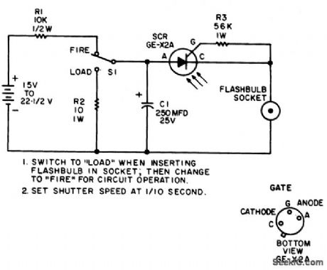
Light-triggered photoflash slave. This circuit is activated when you operate your camera's flash. If a 22.5-volt battery is not available use two 9-volt batteries. To increase the LASCR sensitivity mount it behind a lens or reflector (courtesy General Electric Company). (View)
View full Circuit Diagram | Comments | Reading(1253)
173_MC_POWER_AMPLIFIER
Published:2009/7/10 5:28:00 Author:May
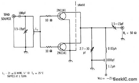
Uses two 2N-1141's in parttllel to deliver average of 400 mw, with power gain of 11.5 db and collector efficiency of 42%. Has excellent large signal performance.-Texas Instruments Inc., Solid-State Communications, McGraw.Hill, N.Y., 1966, p 320. (View)
View full Circuit Diagram | Comments | Reading(688)
RF_OUTPUT_INDICATOR
Published:2009/7/10 5:28:00 Author:May

A simple RF detector circuit using a visual indicator can be useful for an RF output indicator, etc.This circuit was used for a transmitter ON indicator. (View)
View full Circuit Diagram | Comments | Reading(0)
DOUBLE_BOOTSTRAPPED_FET
Published:2009/7/10 5:26:00 Author:May
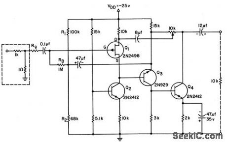
Both drain and source are bootstrapped in 6-db high-input-impedance amplifier, to reduce effect of fet capacitances so they are insignificant compared to stray circuit capacitances at input terminal. 10-K pot provides gain compensation adiustment.-L. J. Sevin, Jr., Field-Effect Transistors, McGraw-Hill, N.Y., 1965, p 69. (View)
View full Circuit Diagram | Comments | Reading(640)
MODULATION_MONITOR
Published:2009/7/10 5:25:00 Author:May

Suitable for AM transmitters, this circuit uses neon lamps to indicate 50%, 85%, and 100% mod-ulation on negative peaks. (View)
View full Circuit Diagram | Comments | Reading(0)
FLIP_FLOP_INDEPENDENT_LAMP_DRIVER
Published:2009/7/10 5:25:00 Author:May
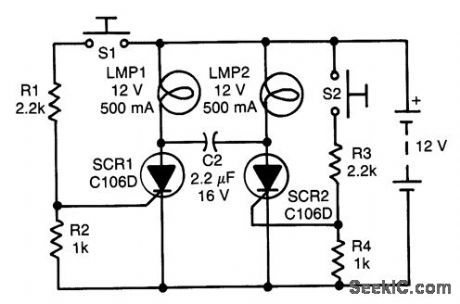
Assume first that SCRt is on and SCR2 is off so that C1 is fully charged, with its LMP2 end positive. The state of the circuit can be changed by pressing S2. As SCR2 turns on, it turns SCR1 off capacitively via its anode. Capacitor C1 then recharges in the opposite manner (i.e., the left end is now positive). The state of the circuit can be changed again by pressing S1, thus driving SCR1 on by way of its gate, and driving SCR2 off capacitively via its anode. (View)
View full Circuit Diagram | Comments | Reading(700)
WIDEBAND_AMPLIFIER
Published:2009/7/10 5:24:00 Author:May
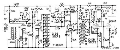
Twin.T ampliler is used between crystal detector and cro of microwave spectrometer for studying electron resonance phenomenon in pctramagnetic materials.-R. R. Unterberger, Microwave Spectrometer Tests Electron Resonance, Elecronics, 32:11, p 142-144.
(View)
View full Circuit Diagram | Comments | Reading(0)
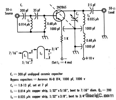
UHFSOURCEDIPPER
Published:2009/7/10 5:24:00 Author:May
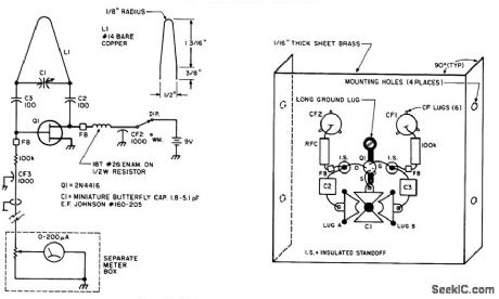
This dipper is useful for UHF experiments in the 420-to-450 MHz amateur band. Because layout can affect performance, follow Fig. 48-2(b) (View)
View full Circuit Diagram | Comments | Reading(827)
025_W_AMPLIFIER
Published:2009/7/10 5:23:00 Author:May
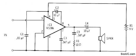
Single Radio Shack RS386 IC powered by 6-9 V from battery provides gain of about 200 with sufficient power to drive 8-ohm loudspeaker when speaking closely into small dynamic microphone of type used with portable tape recorders.-F. M. Mints, Integrated Circuit Projects, Vol. 2, Radio Shack, Fort Worth, TX, 1977, 2nd Ed., p 87-95. (View)
View full Circuit Diagram | Comments | Reading(746)
100_MC_CASCADED
Published:2009/7/10 5:23:00 Author:May
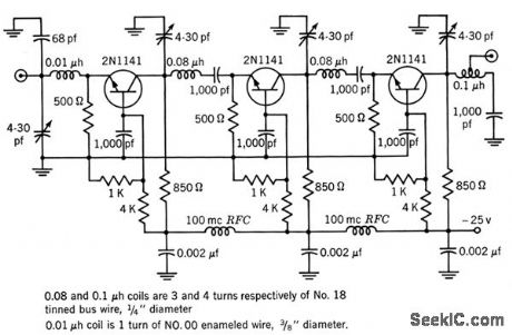
Uses mismatch design technique to obtain desired overall gain of 37.5 db at bandwidth of 9 Mc for three cascaded stages.-Texas Instruments Inc., Transistor Circuit Design, McGraw-Hill, N.Y.,1963,p 290. (View)
View full Circuit Diagram | Comments | Reading(716)
250_MC_R_F_FOR_MILITARY_VHF_BAND
Published:2009/7/10 5:22:00 Author:May
Gives 12.5 db gain and noise figure of only 5 db, with excellent stability.-Texas Instruments Inc., solid-State Communications, McGraw-Hill,N.Y.,1966,p 297. (View)
View full Circuit Diagram | Comments | Reading(695)
WIDEBAND_UNITY_GAIN_FET
Published:2009/7/10 5:21:00 Author:May
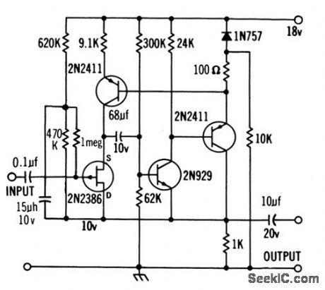
Input impedance is about 100 meg, and response is within 3 db from below 10 cps to 1 Mc for 100K generator resistance.-Texas Instruments Inc., Solid-State Communications, MAcGraw-Hill, N.Y., 1966, p 296. (View)
View full Circuit Diagram | Comments | Reading(812)
| Pages:815/2234 At 20801802803804805806807808809810811812813814815816817818819820Under 20 |
Circuit Categories
power supply circuit
Amplifier Circuit
Basic Circuit
LED and Light Circuit
Sensor Circuit
Signal Processing
Electrical Equipment Circuit
Control Circuit
Remote Control Circuit
A/D-D/A Converter Circuit
Audio Circuit
Measuring and Test Circuit
Communication Circuit
Computer-Related Circuit
555 Circuit
Automotive Circuit
Repairing Circuit