
Circuit Diagram
Index 806
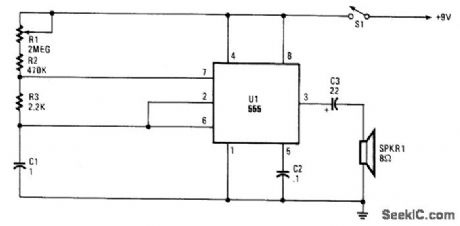
METRONOME_II
Published:2009/7/10 21:21:00 Author:May
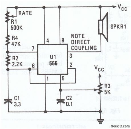
This electronomic metronome, using a 555 oscillator/timer, provides 10 to 40 beats per minute. The frequency is controlled by R3. (View)
View full Circuit Diagram | Comments | Reading(668)
INCUBATOR_MOTOR_CONTROLLER
Published:2009/7/17 4:17:00 Author:Jessie
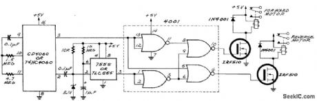
The circuit has a 4060 CMOS long-period timer, which consists of an oscillator plus a series of binary counters that divide the frequency by 2, 4, 8, etc. up to 16,384. The oscillator runs at a comfortable 2 Hz (2 cycles per second), controlled by a capacitor and two resistors, and the binary counter divides this to produce a square wave that has only one cycle every 2 hours, as well as another one that oscillates twice as fast. The faster of the two square waves determines when the motor runs, and the slower one determines its direction. Here's how it's done: First, the faster square wave goes through a capacitor, resistor, and diode, which convert it into a narrow negative-going pulse that occurs once per hour. The 555, connected as a monostable, stretches the short pulse so that it is 10 s long (the length of time the motor should run). Logic gates then steer that pulse to one of two relays so that the motor runs either forward or backward, depending on which state the slow square wave is in at the time. Because the forward and reverse pulses are generated by the same 555 circuit, they are the same length-this is important so that the reverse cycle will exactly undo the motion of the forward cycle. (View)
View full Circuit Diagram | Comments | Reading(2048)
ABSOLUTE_TE_MPERATURE_SENSING
Published:2009/7/10 21:20:00 Author:May
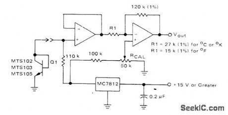
Silicon temperature sensor (MTS102, MTS103, or MTS105) provides precise temperature-sensing accuracy over range of -40℃to +150℃. Sensor is essentially a transistor with base and collector leads connected together externally; baseemitter voltage drop then decreases linearly with temperature over operating range. Voltage change is amplified by two opamps in series, operating from regulated output of MC7812 regulator. Opamp types are not critical, With Q1 at known temperature, adjust 50K pot to give output voltage equal to TEMP x10 mV. Output voltage is then10 mV per degree in desired temperature scale.- Silicon Temperature Sensors, Motorola, Phoenix, AZ, 1978, DS 2536. (View)
View full Circuit Diagram | Comments | Reading(1426)
Norton_amplifier_with_dc_gain_control
Published:2009/7/17 4:17:00 Author:Jessie
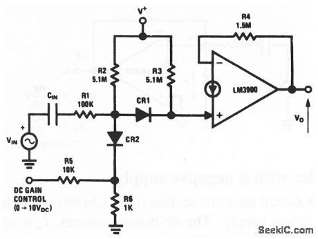
This circuit uses one section of an LM3900 to form an ac amplifier with a variable gain control. The dc gain-control input ranges from 0 V for minimum gain to about 10 V for maximum gain. National Semiconductor Linear Applications Handbook, 1991 p.221 (View)
View full Circuit Diagram | Comments | Reading(1081)
SIMPLE_ELECTRONIC_METRONOME
Published:2009/7/10 21:20:00 Author:May
Two complementary transistors form a simple oscillator whose frequency range is from about 0.5 to several Hz. This circuit is useful as a metro-nome, timer, or pacer for exercise equipment. (View)
View full Circuit Diagram | Comments | Reading(761)
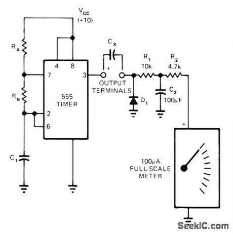
Frequency_doubler_with_linear_amplitude_response_
Published:2009/7/17 4:16:00 Author:Jessie
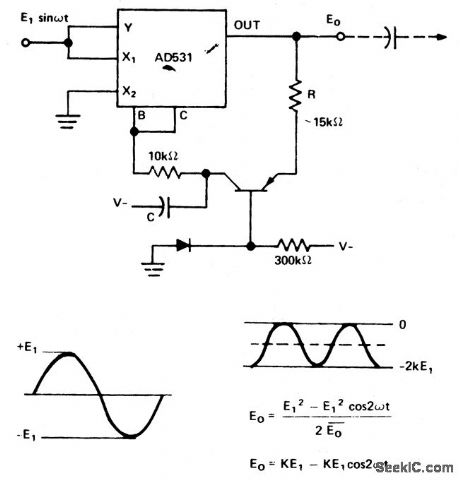
Frequency doubler with linear amplitude response (courtesy Analog Devices, Inc.). (View)
View full Circuit Diagram | Comments | Reading(932)
0_10O℃_WITH_1°ACCURACY
Published:2009/7/10 21:18:00 Author:May
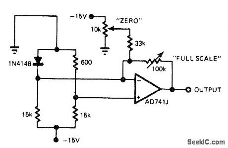
Low-cost diode serves as temperature sensor. To calibrate, place diode in 0℃environment and adjust zero pot for 0-V output, then place diode in 100℃ environment and adjust full-scale pot for 10-V output. Repeat procedure until interaction between adjustments ceases.-J. Williams, Designer's Guide to: Temperature Measurement, EDN Magazine, May 20, 1977, p 71-77. (View)
View full Circuit Diagram | Comments | Reading(1173)
Monostable_multivibrator
Published:2009/7/17 4:15:00 Author:Jessie
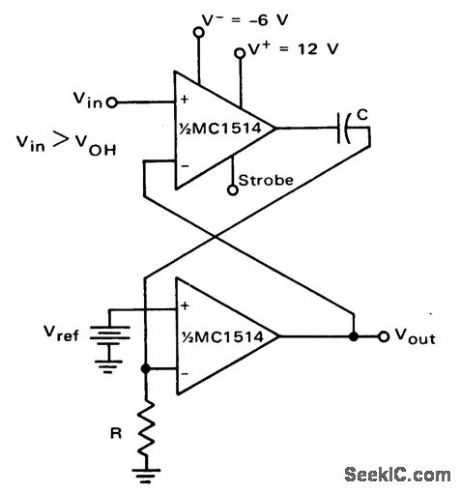
Monostable multivibrator (courtesy Motorola Semiconductor Products Inc.). (View)
View full Circuit Diagram | Comments | Reading(0)
METRONOME_I
Published:2009/7/10 21:18:00 Author:May
This simple metronome circuit offers a range of speeds from largo to prestissimo!The parts values are set so that the repetition rate adjusted by R1 runs from nearly 45 to 184 per minute. (View)
View full Circuit Diagram | Comments | Reading(0)
250_KW_MODULATOR
Published:2009/7/17 4:15:00 Author:Jessie
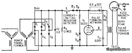
Ten silicon diodes replace five vacuum tubes in artificicd line. type modulator for airborne radar operating at peak power of 250 kw.-M..G. Gray, Using Silicon Diodes in Radar Modulators, Electronics, 32:24, p 70-72. (View)
View full Circuit Diagram | Comments | Reading(769)
BOUNCE_FREE_AUTO_REPEAT_SWITCH
Published:2009/7/10 21:17:00 Author:May
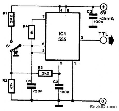
This switch that keeps pulsing as long as it is pressed is often required. The circuit here used the well known Type 555 for this purpose. Its output is a TTL-compatible signal. Pin 5 of the timer has a potential of 67% of the supply voltage, UCC In the quiescent condition (switch not pressed), C1 charges via R2 and R3 to a voltage that is lower than that at pin 5, and thus is also lower than the toggle voltage.When the switch is pressed, C1 is rapidly charged via R1 to the toggle voltage, upon which the timer emits a pulse. At the same time, the capacitor is discharged again via R4. As long as the switch is pressed, the circuit functions as an astable toggle and produces pulses. When it is released, the capacitor cannot charge to the toggle voltage. (View)
View full Circuit Diagram | Comments | Reading(833)
H_BRIDGE_MOTOR_DRIVE_CIRCUIT
Published:2009/7/17 4:14:00 Author:Jessie
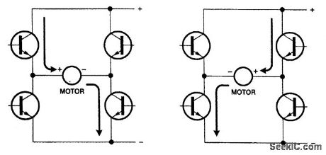
An H bridge can run a dc motor in either direction by turning on two transistors at a time. An H bridge is a circuit that supplies power to a motor and can reverse its polarity. It is usually used to run a dc motor forward and backward. (View)
View full Circuit Diagram | Comments | Reading(2274)
TRANSISTOR_SENSOR_1
Published:2009/7/10 21:17:00 Author:May
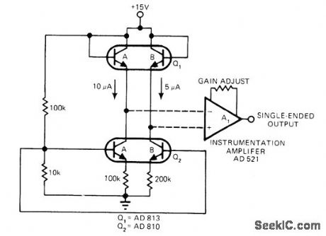
Current-ratio differential-pair temperature sensor uses dual transistor Q1. Difference between base-emitter voltages of Q1A and Q1B varies linearly with temperature, when dual transistor Q2 provides 10μA through Q1A and 5μA through Q1B. Instru-mentation opamp provides single-ended output with better than 1℃ accuracy over 300℃ temperature range. Analog Devices AD 590 IC version of differential pairwill operate overwire line thousands of feet away from instrumentation opamp, for remote sensing.-J, Williams, Designer's Guide to: Temperature Sensing, EDN Magazine, May 5, 1977, p 77-84. (View)
View full Circuit Diagram | Comments | Reading(2764)
One_shot_multivibrator_using_a_UJT_1
Published:2009/7/17 4:14:00 Author:Jessie
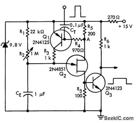
One-shot multivibrator using a UJT (courtesy Motorola Semiconductor Products Inc.). (View)
View full Circuit Diagram | Comments | Reading(748)
LOW_POWER_METRONOME
Published:2009/7/10 21:16:00 Author:May
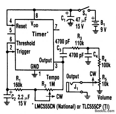
Using only 0.25 mA,this metronome is idealfor battery operation.The tempo range is 34 to 246beats per mtnute.Use a CMOS timer, such as an LM555 CN Or TLC55CP. (View)
View full Circuit Diagram | Comments | Reading(1416)
6_DIGIT_VALUES
Published:2009/7/10 21:14:00 Author:May
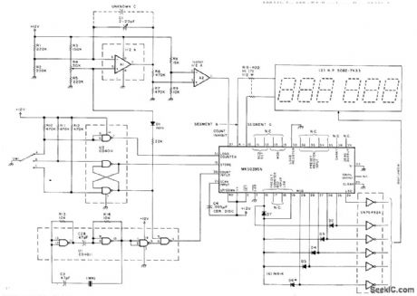
Digital capacitance meter provides display of capacitance values from 1 pF to 999999 pF (1.0μF). Start-measurement switch drains charge from capacitor under measurement and diverts constant-current source to ground. Capacitor begins charging,and counter accumulates 1-μs pulses from crystal clock. When capacitor charge voltage reaches threshold of countinhibit line for counter, contents of counter are displayed as capacitance value. Circuit uses Mostek MK50395N six-decade counter that provides ;-segment output data for display. Position A of SW1 is starting point B stores data in counter display after capacitor measurement, and C initiates measurement. Display includes leading-zero suppression.-J. Garrett,What's Your μF?, 73 Magazine, Dec. 1978, p 234-235. (View)
View full Circuit Diagram | Comments | Reading(3539)
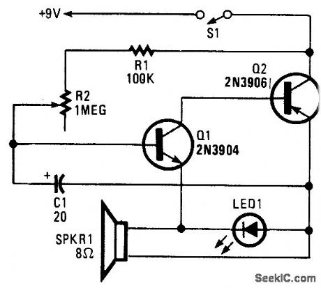
ACOUSTIC_SOUND_RECEIVER
Published:2009/7/10 21:13:00 Author:May
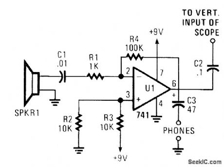
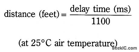
The receiver is an audio amplifter fed by SPKR1, a piezo speaker that is used as a microphone. A scope or headphones can be used as a detector. The scope can be triggered horizontally by the transmitted acoustic pulse; the vertical display can be used to drive the delay time, and hence the distance.
(View)
View full Circuit Diagram | Comments | Reading(1370)
SIMPLE_LCD_DISPLAY_POWER_SUPPLY
Published:2009/7/10 21:12:00 Author:May
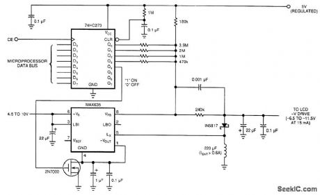
Laptop computers often use large-screen LCDs, which require a variable and a negative supply to ensure maximum contrast. This circuit operates from the system's positive battery supply and generates a digitally variable negative voltage to drive the display.
This figure's switching regulator creates a negative voltage from the battery supply. The microproces-sor data bus drives a 4-bit DAC, which in turn varies the actual regulator output from -6.5 to -11.5 V. This arrangement allows a staircase of 16 possble voltages between these limits.the DAC by using the rail-to-rerail output-drive capability of a 74 HC-series CMOS gate. A resistor divider network formed by the 240-kΩ resistor, connected to the -V filter capadtor and the resistors, is refer-enced to the 5-V supply control (the MAX635 regulator).
When the voltage at the VfB pin is greater than ground, the switching regulator turns on. The inductor dumps this energy into the -V filter capacitor. When the voltage at VFB is less than ground, the regulator skips a cycle. The MAX635 regulates the voltage at the junction of the resistor divider to 0 V. Thus, any resistor that the DAC connects to ground (logic 0) will not contribute any current to the ladder. Only the resistors that are at 5 V (logic 1) will be part of the voltage-divider equation.The entire switching-regulator supply draws less than 150 uA. You can place the circuit in an even lower power mode by interrupting the ground pin. The high-current path is from the battery input through the internal power PMOSFET to the external inductor. Disconnecting the ground connection simply dis-ables the gate drive to the FET and turns off the internal oscillator. (View)
View full Circuit Diagram | Comments | Reading(808)
MECHANICALLY_CONTROLLED_BISTABLE
Published:2009/7/10 21:12:00 Author:May
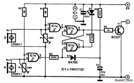
Applications for this mechanically set and reset bistable are found, among others, in antitheft devices and model railway crossings.The transducers are formed by buzzer BZ1, which sets the bistable, and BZ2, which resets it. Their sensitivity is set with P1 and P2, respectively. The presets are adjusted correctly if the output of buffers IC1A and IC1B just toggles from high to low or vice versa.If all have been set correctly, a slight tap of BZ1 will set the bistable. This tap causes T1 to switch on, which enables, for instance, a relay to be energized. At the same time, D1 lights. A tap on BZ2 or on its mounting resets the bistable, whereupon D1 goes out and T1 is switched off. (View)
View full Circuit Diagram | Comments | Reading(696)
BRIDGE_FOR_25_pF_TO_10_μF
Published:2009/7/10 21:11:00 Author:May
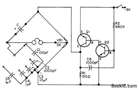
Uses five reference capacitors, one for each range. Linear pot VR1 serves for balancing. High-resistance headphones indicatenull, and capacitor value is then read from setting of VR1. Scale of VR1 is marked for 100 to 10,000 pF for C2 range and 0.01 to 1 μF for C4 range. Scale values are multiplied or divided for other ranges. Calibration is carried out on C2 range, using known capacitor values.Tone oscillator can use almost any pair of transistors, one NPN and the other PNP,-F. G.Rayer, Adrift over Your C's?, 73 Magazine, March 1976, p 106-107. (View)
View full Circuit Diagram | Comments | Reading(965)
| Pages:806/2234 At 20801802803804805806807808809810811812813814815816817818819820Under 20 |
Circuit Categories
power supply circuit
Amplifier Circuit
Basic Circuit
LED and Light Circuit
Sensor Circuit
Signal Processing
Electrical Equipment Circuit
Control Circuit
Remote Control Circuit
A/D-D/A Converter Circuit
Audio Circuit
Measuring and Test Circuit
Communication Circuit
Computer-Related Circuit
555 Circuit
Automotive Circuit
Repairing Circuit