
Circuit Diagram
Index 804
COMPUTERIZED_METER
Published:2009/7/10 21:30:00 Author:May
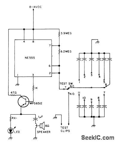
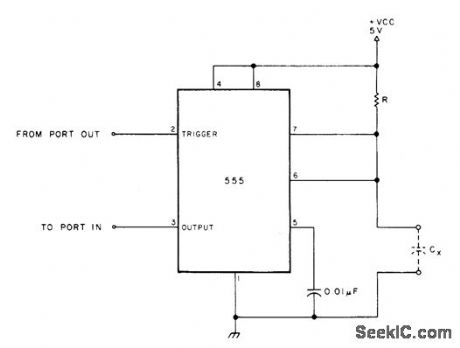
With 4.7 megohms for R, simple 555 timer circuit used in conjunction with computer measures capacitors in five ranges from below 100 pF to 0.1 μF. For larger range, resistor value can be changed. Article includes BASIC software suitable for 8080.based FROM PORT our systems, including calibration program based on known values of capacitance. 555 mono MVBR is triggered under control of computer output port bit, with count being made while mono is timing out. Count is averaged over ten triggerings, then multiplied in computer by calibration factor to give capacitance value. Any desired type of output indicator can be used.-J. Eccleston, Computerized Capacity Meter, 73 Magazine, July 1978, p 88-89. (View)
View full Circuit Diagram | Comments | Reading(888)
Norton_pulse_generator
Published:2009/7/17 4:30:00 Author:Jessie
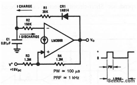
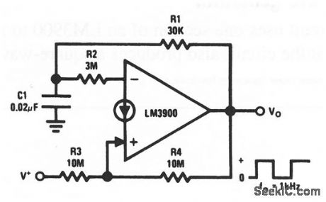
This circuit uses one section of an LM3900 to form a pulse generator (with a 1-kHz pulse repetition rate or frequency, and a 100-μs pulse width). (View)
View full Circuit Diagram | Comments | Reading(795)
CAVE_MAPPING_RECEIVER
Published:2009/7/17 4:29:00 Author:Jessie
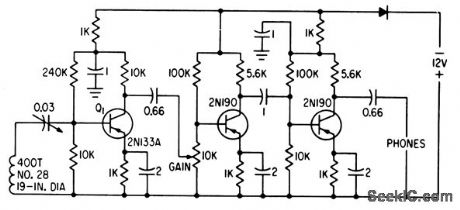
Pickup loop feeds low-noise transistor Q1, followed by twostage audio amplifier. Since low-frequency magnetic field (2 kc) is attenuated very little by rock, soil, or water, strength of received signal from transmitter in cave being mapped can be measured. When system is calibrated for distance on surface, depth can be measured.-E. R. Roeschlein, Mapping Caves Magnetically, Electronics, 33:39, p 61. (View)
View full Circuit Diagram | Comments | Reading(982)
FAR_END_OF_LINE_MODULATOR_CLIPPER
Published:2009/7/17 4:29:00 Author:Jessie
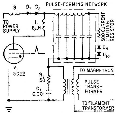
In variation of diode modulator, clipper diodes D9 and D10 are connected to far end of pulse-forming network, for improved perform once. Choke L in plate circuit of thyratron limits rate of rise of thyratron current.-M. G. Gray, Using Silicon Diodes in Radar Modulators, Electronics, 32:24, p 70-72. (View)
View full Circuit Diagram | Comments | Reading(1666)
PULSE_WIDTH_ENCODER
Published:2009/7/17 4:28:00 Author:Jessie
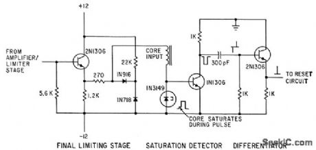
Pulse widths in microsecond range are amplitude-limited and dumped into magnetic core. When core saturates, signal is recorded on magnetic tape and core is reset for next series of pulses. The number of changes of state between saturation points gives the number of pulses for core saturation, from which pulse width can be computed.-W. L. Carter and P. J. Knoke, Pulse-Width Measurements, Electronics, 35:43, p 51-53. (View)
View full Circuit Diagram | Comments | Reading(793)
LOG_AMPLIFIER
Published:2009/7/17 4:28:00 Author:Jessie
Has highly linear logarithmic output over 30-db dynamic range. Used in obtaining antenna patterns on operating radar system. Output current is directly proportional lo pulse repetition frequency and log of peak r-f pulse power-Logaritthmic Amplifier for Radar Signals, Electronic Circuit Design Handbook, Mactier Pub. Corp., N.Y., 1965, p 107. (View)
View full Circuit Diagram | Comments | Reading(0)
A_C_AMPLIFIER_FOR_SWR_METER
Published:2009/7/17 4:27:00 Author:Jessie
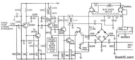
Collector of Q3 provides d-c offset current required for expanding ct segment of the 10-db scale of the meter. Gain adjustment permits any of the four 2.5-db expand ranges to give a full-scale reading.-D. L. Howard, Drift Control Allows Expansion Scales for SWR Meter, Electronics, 35:21, p 45-47. (View)
View full Circuit Diagram | Comments | Reading(734)
Norton_square_wave_oscillator
Published:2009/7/17 4:26:00 Author:Jessie
This circuit uses one section of an LM3900 to form a square-wave oscillator (with a 1-kHz output using the values shown). National Semiconductor Linear Applications Handbook 1991 p 232 (View)
View full Circuit Diagram | Comments | Reading(918)
EKG_input_amplifier_using_an_optically_coupled_3652_HG_isolation_amplifier_to_protect_the_patent_from_possible_lethal_potentials_
Published:2009/7/17 4:26:00 Author:Jessie
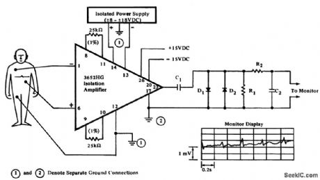
EKG input amplifier using an optically coupled 3652 HG isolation amplifier to protect the patent from possible lethal potentials (courtesy Burr-Brown Research Corporation). (View)
View full Circuit Diagram | Comments | Reading(2486)
COSINE_SQUARED_PULSE_GENERATOR
Published:2009/7/17 4:26:00 Author:Jessie
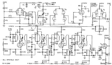
Generates pulse whose width is half the duration. of one input sine-wave cycle. Cosine-squared pulse output is fed into balanced modulator in conjunction with 30-Mc signal, and resulting burst is used as input to synchrodyne, klystron.-K. H. Chase and J. L Pierzga Reducing Mutual Radar Interference, Electronics, 32:28, p 39-43. (View)
View full Circuit Diagram | Comments | Reading(765)
Norton_sine_wave_oscillator
Published:2009/7/17 4:26:00 Author:Jessie
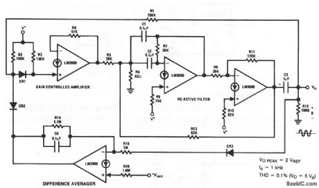
This circuit uses four sections of an LM3900 to form a sine-wave oscillator. One section is used as a gain-controlled amplifier (to sustain feedback), and another section is a difference averager that maintains a constant output level.The remaining sections are connected as an RC active filter (to produce a 1-kHz output with the values shown). National Semiconductor Linear Applications Handbook 1991 p 231 (View)
View full Circuit Diagram | Comments | Reading(1144)
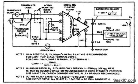
Multilead_EKG_recorder_input_circuitry_using_a_284J_isolation_amplifier
Published:2009/7/17 4:25:00 Author:Jessie
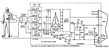
Multilead EKG recorder input circuitry using a 284J isolation amplifier (courtesy Analog Devices, Inc.). (View)
View full Circuit Diagram | Comments | Reading(1318)
TIMING_PULSE_SHAPER
Published:2009/7/17 4:24:00 Author:Jessie
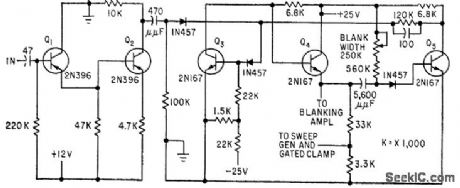
Monostable mvbr converts timing signal to narrow pulse whose width is accurately controlled by R-C net work. Use of emitter-follower Q4 between triggered transistor Q3 and R-C network assures fast rise and fall times.-C. E. Veazie, Transistorized Radar Sweep Circuits Using Low Power, Electronics, 32:26, p 46-47. (View)
View full Circuit Diagram | Comments | Reading(651)
TUNNEL_DIODE_PARAMETERS
Published:2009/7/17 4:24:00 Author:Jessie
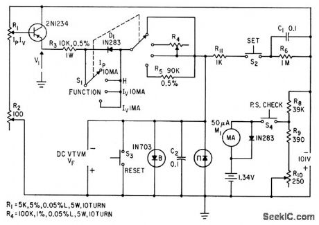
Provides quantitative measurement of all d-c parameters for the three regions of forward d-c characteristic curve for tunnel diodes.-C. D. Todd, Simple Test Sets Measure Tunnel-Diode Parameters, Electronics, 35:14, p 43-45. (View)
View full Circuit Diagram | Comments | Reading(712)
Norton_regulator_with_high_voltage_input_protection
Published:2009/7/17 4:24:00 Author:Jessie
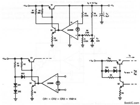
This circuit uses one section of an LM3900 as the control element in a voltage regulator. Q1 and Q2 absorb any high input voltages, and therefore must be high-voltage transistors. With the values shown, the output is about 8.2 V.Diodes can be added (as shown in Fig.11-42B) to reduce ripple feedthrough and input-voltage dependence. Short-circuit protection can also be added, as shown in Fig. 11 -42C. National Semiconductor Linear Applications Handbook, 1991, p. 225 226 (View)
View full Circuit Diagram | Comments | Reading(903)
Isolation_amplifier_for_biomedical_and_industrial_applications
Published:2009/7/17 4:24:00 Author:Jessie
Isolation amplifier for biomedical and industrial applications.(courtesy Analog Devices, Inc.). (View)
View full Circuit Diagram | Comments | Reading(1002)
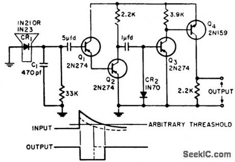
LOGARITHMIC_ATTENUATOR
Published:2009/7/17 4:24:00 Author:Jessie
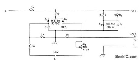
Output of pas sive circuit is proportional to log of input voltages between 0.1 and 100 v. Serves for either positive or negative pulses.-C. D. Nail, Logarithmic Attenuator Spans Three Decades, Electronics, 36:46, p 47-48. (View)
View full Circuit Diagram | Comments | Reading(694)
Norton_direct_coupled_unity_gain_buffer
Published:2009/7/17 4:23:00 Author:Jessie
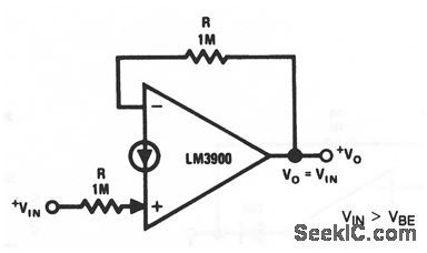
This circuit uses one section of an LM3900 to form a simple direct-coupled unity-gain buffer. Notice that the input voltage must be greater than one VEB (about 0.5 V), but less than the maximum output swing. National Semiconductor. Linear Applications Handbook, 1991 p 224 (View)
View full Circuit Diagram | Comments | Reading(728)
YOKE_DRIVER
Published:2009/7/17 4:23:00 Author:Jessie
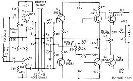
Used to damp sweep signal voltage to reference voltage during clamping time at end of sweep, while removing clamp during sweep. Diodes D1-D2 and D3-D4, con netted in opposite polarity to each signal line, serve as clamp circuit.-C. E. Veazie, Transistorized Radar Sweep Circuits Using Low Power, Electronics, 32:26, p 46-47. (View)
View full Circuit Diagram | Comments | Reading(747)
Fetal_heartbeat_monitoring_input_circuitry_using_an_Analog_Devices_284J_isolation_amplifier_
Published:2009/7/17 4:22:00 Author:Jessie
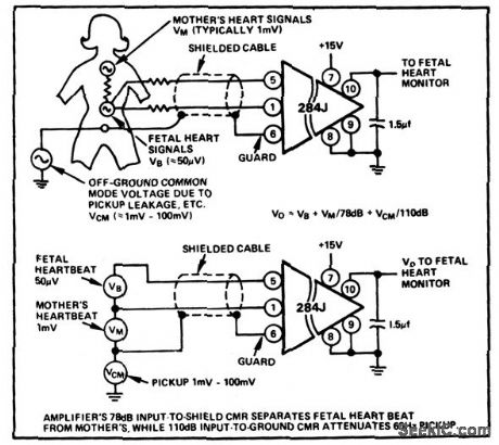
Fetal heartbeat monitoring input circuitry using an Analog Devices 284J isolation amplifier (courtesy Analog Devices, Inc.). (View)
View full Circuit Diagram | Comments | Reading(2320)
| Pages:804/2234 At 20801802803804805806807808809810811812813814815816817818819820Under 20 |
Circuit Categories
power supply circuit
Amplifier Circuit
Basic Circuit
LED and Light Circuit
Sensor Circuit
Signal Processing
Electrical Equipment Circuit
Control Circuit
Remote Control Circuit
A/D-D/A Converter Circuit
Audio Circuit
Measuring and Test Circuit
Communication Circuit
Computer-Related Circuit
555 Circuit
Automotive Circuit
Repairing Circuit