
Circuit Diagram
Index 1186
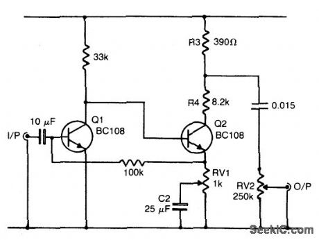
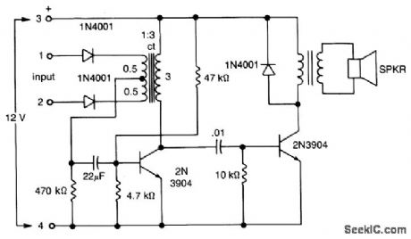
FUZZ_BOX_3
Published:2009/7/1 3:47:00 Author:May
Circuit Notes
Q1 and Q2 form a voltage amplifier which has sufficient gain to be overdriven by a rela-tively low input, such as an electric guitar. The result is that the output from Q2 is a Squared-Off verson of the input, giving the required fuzz sound. RV1 adjusts the amount of negative feedback inserted into the circuit by C2, and thus the amount of squaring of the signal. The purpose of R3 and R4 is to lower the output voltage to a suitable level, which is then ad-justed as required with the volume control VR2. (View)
View full Circuit Diagram | Comments | Reading(1026)
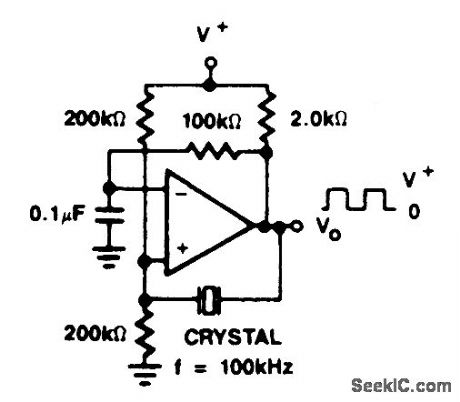
CRYSTAL_CONTROLLED_OSCILLATOR
Published:2009/7/1 3:43:00 Author:May
View full Circuit Diagram | Comments | Reading(0)
MAGNETIC_TRANSDUCER_PREAMP
Published:2009/7/24 4:31:00 Author:Jessie
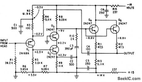
Gain is constant at 49 within 2% for ac source impedances ranging front 0 to 5,000 ohms, such as magnetic read heads. Gain remains con stunt within 3 db from 10 cps to 1 Mc.-S. R. Parris, Wideband Transistor Preamplifier Handles Low-Resistance Transducers, Electronics, 34:11, p 57-59. (View)
View full Circuit Diagram | Comments | Reading(1051)
ALARM_CIRCUIT
Published:2009/7/1 3:43:00 Author:May
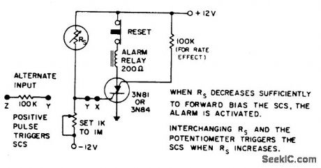
Temperature, light, or radiation sensitive resistors up to 1 megohm readily trigger the alarm when they drop below the value of the preset potentiometer. Alternately, 0.75 V at the input to the 100 kΩ triggers the alarm. Connecting SCS between ground and -12 V permits triggering on negative input to GA. (View)
View full Circuit Diagram | Comments | Reading(955)
COLPITTS_OSCILLATOR
Published:2009/7/1 3:42:00 Author:May
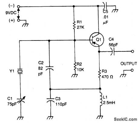
Bias for the pnp bipolar transistor is provided by resistor voltage divider network R1/R2. The collector of the oscillator transistor is kept at ac ground by capacitor C5, placed close to the transistor. Feedback is provided by capacitor voltage divider C2/C3. (View)
View full Circuit Diagram | Comments | Reading(0)
Instrumentation_amplifier_with_300_V_common_mode_range
Published:2009/7/24 4:06:00 Author:Jessie
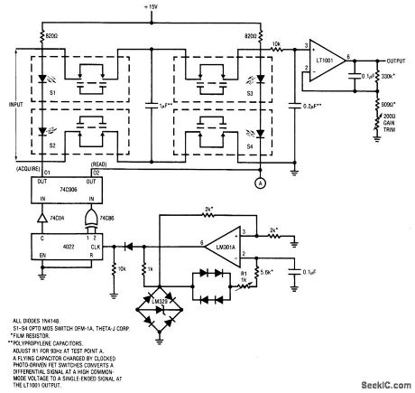
Fig. 14-20 This circuit will withstand common-mode voltages of 1300 V and provide a CMRR of 160 dB or greater (see chapter 10 for coverage of common-mode voltages and CMRR). To trim, adjust R1 for 93 Hz at the LM301A output. Then, adjust the gain-trim pot for the desired gain. This amplifier is particularly useful for transducer signal conditioning, where high common-mode voltages mightexist. Linear Technology Linear Applications Handbook, 1990. p. AN6-2. (View)
View full Circuit Diagram | Comments | Reading(721)
Ultra_low_dropout_regulator
Published:2009/7/24 4:06:00 Author:Jessie
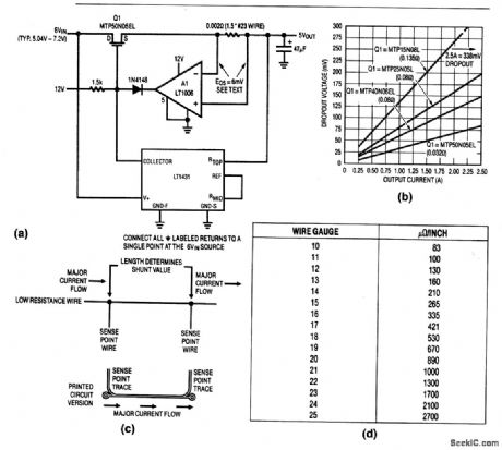
This simple regulator has only 85-mV dropout at 2.5 A. The low dropout makes the circuit particularly suitable for battery-driven laptop computers. The 12V required for the Q1 gate is found (on laptop computers) as the power source for disk drives and other peripherals. The shunt across the A1 inputs provides short-circuit protection. Figure 8-52C shows construction details for the shunt (both PC and wire versions). Figure 8-52D shows resistance versus size for various copper wire sizes. Figure 8-52B shows dropout characteristics for the circuit. (View)
View full Circuit Diagram | Comments | Reading(562)
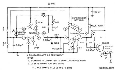
PHOTOELECTRIC_ALARM_SYSTEM
Published:2009/7/1 3:42:00 Author:May

The CA3164A BiMOS detector alarm system and the CA3078 micropower op amp with a photodiode are used as an automatic switch for turning on a night light or sounding a mechanical horn. (View)
View full Circuit Diagram | Comments | Reading(1141)
CROWBAR
Published:2009/7/24 4:06:00 Author:Jessie
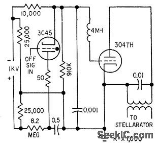
Used to cut off oscillator sharply in lank circuit of stellarator. Consists of lube with plate holdoff rating comparable to peak instantaneous output tank voltage. At end of pulse, grid is driven to +500 V end tube becomes low impedance across lank, to damp out oscillation within a cycle or two.-R. t. Gamblin, Radio-Frequency Circuits for Plasma Physics, Electronics, 32:27, p 50-52. (View)
View full Circuit Diagram | Comments | Reading(1)
ROW_STORAGE_UNIT_FOR_MAGNETIC_CONTOUR_DISPLAY
Published:2009/7/24 4:06:00 Author:Jessie
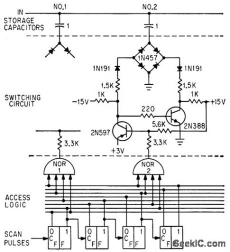
Scan pulses activate nor gates in sequence. For 11 by 11 display matrix, there are 11 nor pates each with its switching circuit. On read-in, nor gate output of -10 V activates switching circuit, grounding its capacitor and making capacitor charge up to value of that data point.-W. W. Anderson, Latest Antisubmarine Aid-Magnetic Contour Display System, Electronics, 36:32, p 58-61. (View)
View full Circuit Diagram | Comments | Reading(722)
TROUBLE_TONE_ALERT
Published:2009/7/1 3:41:00 Author:May
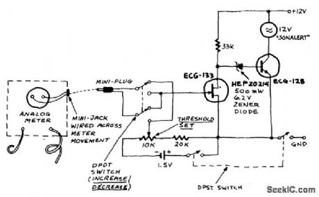
The Trouble Tone Alert is intended for use with analog meters-just wire a mini earphone jack directly across the meter movement, plug it in, and you're all set. This device reacts the to the meter-movement driving voltage. It will respond to a change in ac or dc voltage, current, or in resistance. The circuit will respond to an increase or decrease selected by the DPDT switch and is adjusted with the threshold control until the tone from the Sonalert just disappears (with the meter in the circuit being tested, of course). (View)
View full Circuit Diagram | Comments | Reading(778)
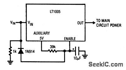
Automatic_shutdown_for_load_shorts
Published:2009/7/24 4:05:00 Author:Jessie
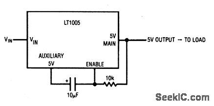
This circuit latches down the main regulator if a short occurs in the load. When power is applied, the auxiliary output comes up and transfers the charge through the capacitor. This forces the enable pin high, and allows the main regulator to come up and power the load. If a load short occurs, the regulator goes into current limit and the main output falls to zero. This pulls the enable pin low and completes a positive-feedback latch to disable the main output. Under these conditions, the output remains at zero-even after the load short is removed. Thus, the regulator need not dissipate power during the short. The output can be reset by removing the regulator input power (VIN) or by forcing the enable pin. (View)
View full Circuit Diagram | Comments | Reading(645)
OVERTONE_CRYSTAL_OSCILLATOR
Published:2009/7/1 3:40:00 Author:May
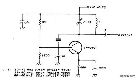
This oscillator is designed for overtone crystals in the 20-100 MHz range operating in the third and fifth mode. Operating frequency is determined by the tuned circuit. (View)
View full Circuit Diagram | Comments | Reading(0)
Capacitive_transducer_signal_conditioner
Published:2009/7/24 4:05:00 Author:Jessie
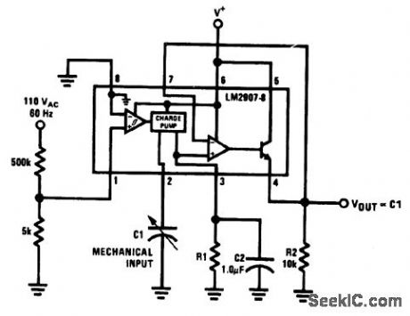
Fig. 14-19 This circuit uses an LM2907 to condition the output of a capacitive transducer, and to mix this output with another variable. If the other signal is fixed at 60-Hz, as shown, then the output is proportional to the capacitive-transducer output only. If the other signal is variable, the transducer acts as a multiplier. For example, in flow-measurement indicators, the input frequency can be a variable that depends on flow rate, such as a signal generated from a paddle wheel, propeller, etc. The capacitive-transducer can be an indication of orifice size or aperture size (such as a throttle). The product of these two indicates volume flow, where the output voltage is proportional to size times rate. A thermistor can be added to R1 to convert the volume flow to mass flow. A combination of these signal-conditioned inputs, including control voltage on the supply, can be used to provide complex analog functions, where several variable or fixed factors must be multiplied. National Semiconductor Linear Applications Handbook, 1991. p. 432. (View)
View full Circuit Diagram | Comments | Reading(1878)
ELECTRIC_FISH_FENCE
Published:2009/7/24 4:05:00 Author:Jessie
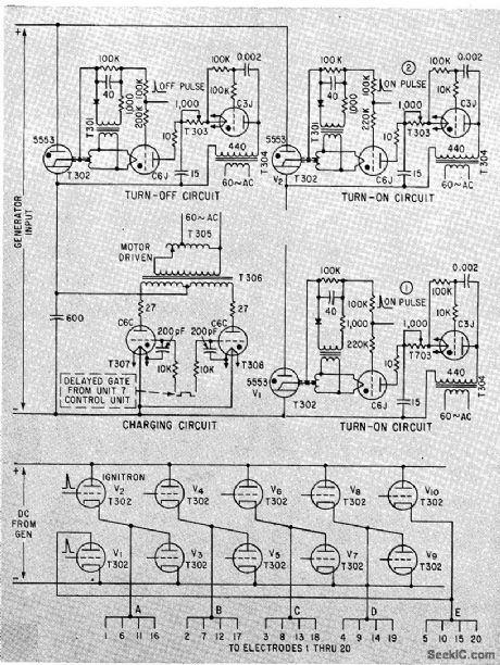
Output of 360-kw d-c generator is applied to row of electrodes in sequence by pair of high. voltage ignitron tubes that runt pulse on and off for each electrode in turn. Single turnoff ignitron terminates pulse period of whichever loaded ignitrons are conducting.-C. D Volz, Ignitron-Pulsed Electric Fence Guides Migrating Salmon, Electronics, 35:16, p 50-52. (View)
View full Circuit Diagram | Comments | Reading(1258)
Power_on_delay
Published:2009/7/24 4:04:00 Author:Jessie
When power is applied to this circuit, the output is held low until the capacitor charges beyond the 1.6-V threshold of the enable pin. With the RC values shown, the time required is about 100 ms. The diode/1-kΩ combination drains the capacitor quickly when power is removed. (View)
View full Circuit Diagram | Comments | Reading(923)
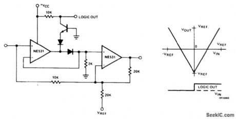
DIFFERENTIAL_VOLTAGE_OR_CURRENT_ALARM
Published:2009/7/1 3:39:00 Author:May
The input may be dc or low frequency ac,The output is a distinctive senes of audiobeeps or a continuous tone,and occurs only when a selected polarity unbalance IS pres-ent at the mput. (View)
View full Circuit Diagram | Comments | Reading(774)
Gasoline_engine_signal_conditioner
Published:2009/7/24 4:04:00 Author:Jessie
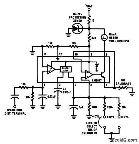
Fig. 14-18 This circuit uses an LM2907 to condition the signals between a gasoline engine and a tachometer. The simple circuit can be set for any number of cylinders by linking the appropriate timing resistor, as shown. The 500-Ω calibration pot is set so that 6000 rpm produces a full-scale indication on a 10-mA meter movement.the zener and resistor ale added as a safety precaution against transients. National Semicondutor Applications Handbook, 1991. p 429 . (View)
View full Circuit Diagram | Comments | Reading(1727)
LOW_FREaUENCY_CRYSTAL_OSCILLATOR_10kHz_to_150_kHz
Published:2009/7/1 3:38:00 Author:May
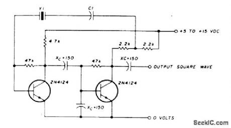

C1 in series with the crystal may be used to adjust the oscillator output frequency. Value may range between 20 pF and 0.01 μF, or may be a trimmer capacitor and will approximately equal the crystal load capacitance. X values are approximate and can vary for most circuits and frequencies; this is also true for resistance values. Adequate power supply decoupling is required; local decoupling capacitors near the oscillator are recommended. All leads should be extremely short in high frequency circuits. (View)
View full Circuit Diagram | Comments | Reading(915)
Precision_high_voltage_instrumentation_amplifier
Published:2009/7/24 4:04:00 Author:Jessie
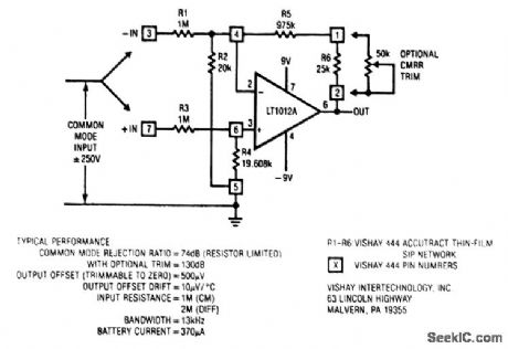
Although this circuit operates with two 9-V batteries, common-mode inputs of ±250 V are possible, with a voltage gain of 1. The circuit will also operate with ±15-V supplies, and with ±1.2-V supplies (with reduced common-mode range, of course). (View)
View full Circuit Diagram | Comments | Reading(807)
| Pages:1186/2234 At 2011811182118311841185118611871188118911901191119211931194119511961197119811991200Under 20 |
Circuit Categories
power supply circuit
Amplifier Circuit
Basic Circuit
LED and Light Circuit
Sensor Circuit
Signal Processing
Electrical Equipment Circuit
Control Circuit
Remote Control Circuit
A/D-D/A Converter Circuit
Audio Circuit
Measuring and Test Circuit
Communication Circuit
Computer-Related Circuit
555 Circuit
Automotive Circuit
Repairing Circuit