
Circuit Diagram
Index 1194
HIGH_FREQUENCY_COMPENSATION
Published:2009/7/24 4:36:00 Author:Jessie
Compensates for 23 db/decade loss above 500 cps, in high-frequency response caused by spacing pickup head 1 mil from magnetic tape of vlf induction radio link.-E. A. Hanysz, J. E. Stevens, and A. Meduvsky, Communication System for Highway Traffic Control, Electronics, 33:42, p 81-83. (View)
View full Circuit Diagram | Comments | Reading(866)
Complete_FM_IF_system_for_high_quality_receivers
Published:2009/7/24 4:35:00 Author:Jessie
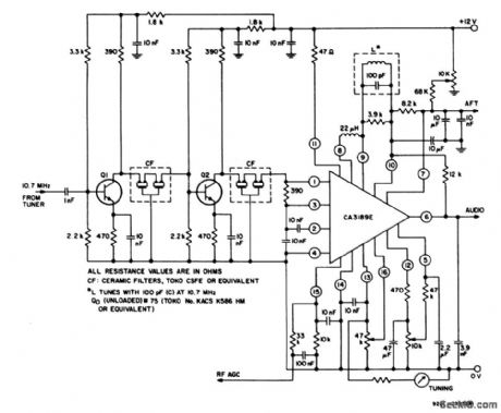
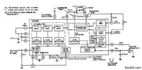
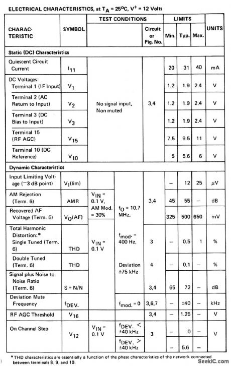
The CA3189 shown in this circuit includes an IF amplifier quadrature detector, AF preamplifier, and specific circuits for AGC, AFC, tuning meter, deviation-noise muting, and on-channel detector, as shown in Fig. 2-61B. Sensitivity is 12μV (typical) at -3-dB point. Typical characteristics are shown in Fig.2-61C (View)
View full Circuit Diagram | Comments | Reading(2035)
Micropower_comparator_with_high_current_switch
Published:2009/7/24 4:35:00 Author:Jessie
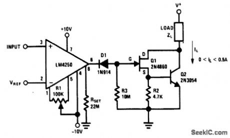
Fig. 15-19 This circuit provides a method of continuously monitoring an input voltage while dissipating only 100μW of power, but still being capable of switching a 500 mA load if the input exceeds a given value. The reference voltage can be any value between +8.5 and -8.5 V. The comparator resolves input voltage differences down into the 0.2-mV region. R1 provides for input-offset null. The load can be a resistor, relay coil, or lamp, so long as load current does not exceed 500 mA. For V+ less than 15 V and IL less than 25 mA, Q2 and R2 can be omitted. National Semiconductor Lineal Applications Handbook 1901, p. 205. (View)
View full Circuit Diagram | Comments | Reading(725)
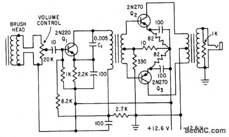
SIRIPF_ON_FILM_RECORD_PLAYBACK
Published:2009/7/24 4:35:00 Author:Jessie
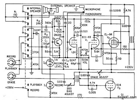
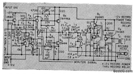
Transistor preamplifier is used only on playback. Two-stage recording amplifier has 10 db of negative feedback from secondary of output transformer to linearize frequency response and reduce distortion. Oscillator V3 supplies bias and erase current al 40 kc.-J. M. Moriarty, It. B. Johnson, and R. J. Roman, Magnetic Sound Track of 8-MM Home Movies, Electronics, 33:35, p 61-63. (View)
View full Circuit Diagram | Comments | Reading(749)
TIMING_SIGNAL_RECORDER
Published:2009/7/24 4:34:00 Author:Jessie
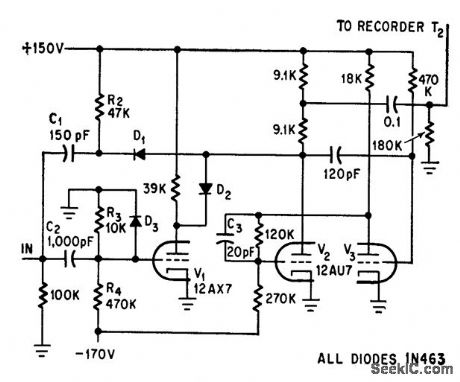
Low-cost analog magnetic rape recorder is modified to store rectangular event-timing signals for biomedical experiments. Input gate signal is differentiated in pulse shaper C1-R2. C2 with R3, R4, and D3 produce alternately positive and negative pulses corresponding to leading and trailing edges of gate. V1, biased off, blocks negative pulses. Output at T2 after inversion by V2 consists of 30-mkrosec negative pulses with peak of 50 V, which can be fed to tape recorder-G. Silverman, Modified Tape Recorder Stores Timing Signals, Electronics, 39:13, p 75-76. (View)
View full Circuit Diagram | Comments | Reading(1073)
Comparator_with_output_buffer
Published:2009/7/24 4:34:00 Author:Jessie

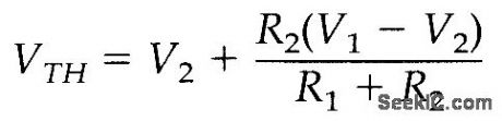

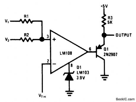
Fig, 15-18 This circuit uses an LM108 op amp as a comparator for voltages opposite polarity. The output changes state when the voltage on the junction R1/R2 is equal to VTH (at pin 2). This is expressed by:
National Semiconductor, Linear Applications Handbook, 1991, p. 71.
(View)
View full Circuit Diagram | Comments | Reading(838)
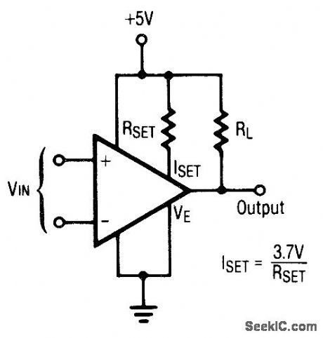
Opposite_polarity_magnitude_comparator
Published:2009/7/24 4:47:00 Author:Jessie
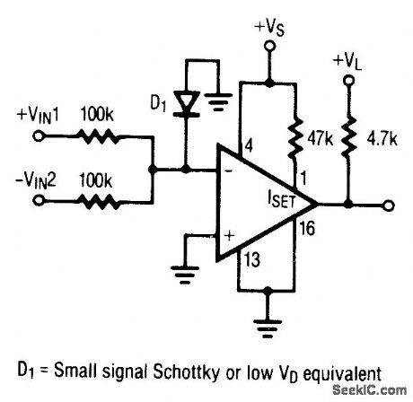
Pig. 15-28 This circuit is similar to that of Fig. 15-22, but it uses only one section of an LP165/365 and it requires a single supply. Figures 15-24B and 15-24C show the pin connections and electrical characteristics, respectively. Raytheon Linear Integrated circuits 1989, p. 5-40. (View)
View full Circuit Diagram | Comments | Reading(728)
MAGNETIC_RECORDER_FOR_8_MM_MOVIE_CAMERA
Published:2009/7/24 4:46:00 Author:Jessie
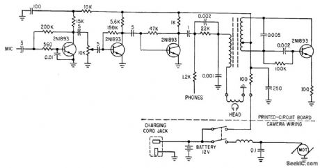
Silicon transistors serve as amplifiers and oscillator for recording on magnetic stripe. Frequency response is 100 to 1,0000 cps.-S. B. Gray, appliances and Housewares, Electronics, 36:20, p 46-49. (View)
View full Circuit Diagram | Comments | Reading(1283)
Extending_high_voltage_three_terminal_regulator_capability
Published:2009/7/24 4:46:00 Author:Jessie
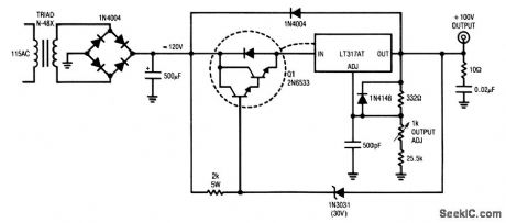
This circuit delivers 100 V at 100 mA and withstands shorts to ground. When an output short occurs, the zener conducts, forcing the Q1 base to 30 V. The Q1 emitter clamps 2 VBE below VZ, well within the VIN/VOUT regulator rating. Q1 sustains 90 VCE at whatever current the transformer and regulator current limit will support. If the regulator and Q1 are thermally coupled, the regulator goes into thermal shutdown and protects the load and regulator as long as the output is shorted. (View)
View full Circuit Diagram | Comments | Reading(795)
Comparator_with_emitter_hysteresis
Published:2009/7/24 4:46:00 Author:Jessie
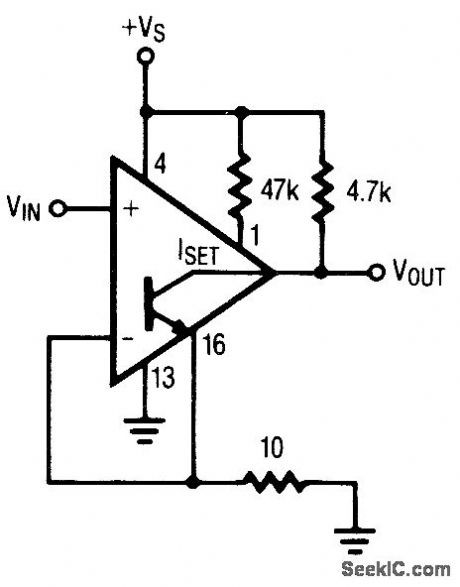
Fig. 15-27 This circuit shows an LP165/365 connected to improve hysteresis (using emitter positive feedback). Notice that this can only be used with one section of the quad LP165/365. Figures 15-24B and 15-24C show the pin connections and electrical characteristics, respectively. Raytheon Linear Integrated circuits 1989 p 5-40. (View)
View full Circuit Diagram | Comments | Reading(819)
INSTRUMENTATION_RECORDER
Published:2009/7/24 4:46:00 Author:Jessie
Bandpass is 250 cps to 250 kc. Uses input emitter-follower, head driver, bias amplifier, and monitor amplifier. Square-wave bias signal is supplied to each channel from master oscillator.-D. R. Steele, More Bandwidth for Magnetic Recorders, Electronics, 33:2, p 44-47. (View)
View full Circuit Diagram | Comments | Reading(827)
Comparator_with_standard_hysteresis
Published:2009/7/24 4:45:00 Author:Jessie
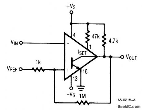
Fig. 15-26 This circuit shows an LP165/365 connected to improve hysteresis (using the standard positive feedback). Figures 15-24B and 15-25C show the pin connections, and electrical characteristics, respectively. Raytheon Linear Integrated Circuits, 1989, p. 5-40. (View)
View full Circuit Diagram | Comments | Reading(828)
ZERO_SPEED_TAPE_PLAYBACK_OSCILLAIOR
Published:2009/7/24 4:45:00 Author:Jessie
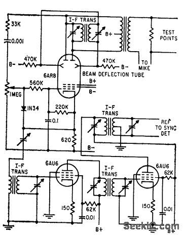
Permits playback of recorded high-frequency signals at exntremely slow speeds so highest frequency component is within limited band. width of pen recorder. 100,kc excitation oscillator and reference amplifier use beam defection tube.-M. E. Anderson, Magnetic Head Reads Tape at Zero Speed, Electronics, 32:10, p 58-60. (View)
View full Circuit Diagram | Comments | Reading(802)
INDEPENDENT_CONTROL_MVBR_TESTS_TRANSPORT
Published:2009/7/24 4:44:00 Author:Jessie
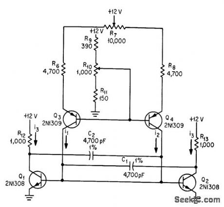
Timing resistors of conventional astable are replaced by adjustable constant-current sources using transistors Q3 and Q4. R7 controls mark/space ratio and R10 con trols frequency.-C. J. Dakin, Novel Multivibrators Test Tape Transports, Electronics, 37:7, p 40-43. (View)
View full Circuit Diagram | Comments | Reading(856)
Comparator_with_TTL_supply_and_TTL_output
Published:2009/7/24 4:44:00 Author:Jessie
Pig. 15-25 This circuit shows an LP165/365 connected for a TTL supply and a TTL output. Figures 15-24B and 15-24C show the pin connections, and electrical characteristics, respectively. Raytheon Linear Integrated Circuits 1989, p. 5-40. (View)
View full Circuit Diagram | Comments | Reading(723)
MEASURING_TAPE_WOW_AND_FLUTTER
Published:2009/7/24 4:44:00 Author:Jessie
Circuit uses 40-kc carrier,calibrated cro,and various spectrum cutout filters to show all drift, wow, and flutter components from d-c to 4,000 cps for magnetic tape recorder.-J. T. Mullin, Precise Measurement of Wow and Flutter, Electronics, 32:26, p 100-102. (View)
View full Circuit Diagram | Comments | Reading(1000)
Comparator_with_split_supply_and_logic_output
Published:2009/7/24 4:43:00 Author:Jessie

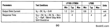
Fig. 15-24 This circuit shows an LP165/365 connected for a split supply, and a logic (TTL) output. Figures 15-24B and 15-24C show the pin connections, and electrical characteristics, respectively. Raytheon Linear Integrated circuits 1989, p. 5-34, 5-36, 5-40. (View)
View full Circuit Diagram | Comments | Reading(706)
12_ns_circuit_breaker_using_a_comparator
Published:2009/7/24 4:41:00 Author:Jessie
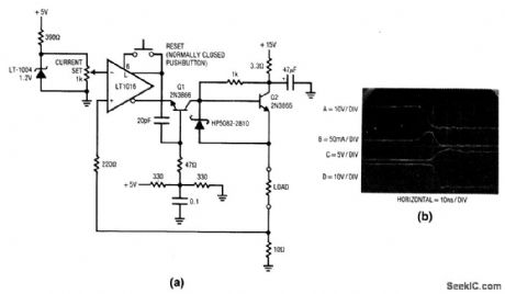
Fig. 15-23 This circuit uses a high-speed comparator (LT1016) to turn off current in a load 12 ns after the load exceeds a preset value. The circuit has been used to protect ICs during development and for protecting expensive loads during calibration. Under normal conditions, the voltage across the 10-Ω shunt is smaller than the potential at the LT1016 inverting input. This keeps Q1 off and Q2 receives bias, which drives the load, When an overload occurs (in this case via a test circuit, trace A, Fig. 15-23B) the current through the 10-Ω sense resistor begins to increase (trace B). When current exceeds the preset value, the LT1016 outputs reverse (the noninverting output is shown in trace C). This provides turn-on drive for Q1 and cuts Q2 off (Q2 emitter is trace D) in 5 ns. The delay from the onset of excessive load current to complete shutdown is 12 to 13 ns. Once the circuit is triggered, the LT1016 is held in the latched state by feedback from the noninverting output. When the load fault is cleared, the pushbutton can be used to reset the circuit. Linear Technology Linear Applications Handbook :990 p. AN13-24. (View)
View full Circuit Diagram | Comments | Reading(703)
Single_supply_fault_monitor
Published:2009/7/24 4:56:00 Author:Jessie
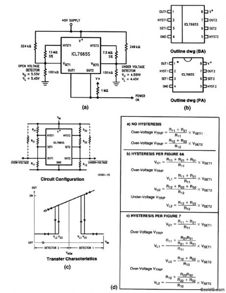
This circuit shows an overvoltage/undervoltage fault monitor for a single supply, using an ICL7665S detector. Figure 9-15B shows the pin connections. The overvoltage trip point is centered around 5.5V, with the undervoltage trip at about 4.5 V. Both points have some hysteresis to prevent erratic output on/off conditions. The two outputs are connected in a wired-Ok signal. Harris Semiconductor, Linear& Telecom ICs, 1991, p 2-131 2137.2138. (View)
View full Circuit Diagram | Comments | Reading(1550)
CRYSTAL_CONTROLLED_BLOCKING_OSCILLATOR
Published:2009/7/24 4:56:00 Author:Jessie
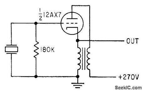
Used for recording 50-kc reference base on magnetic tape in 10-channel instrumentation system. Circuit is ordinary plate-to-cathode coupled blocking oscillator with crystal substituted for capacitor. If free-running frequency (without crystal) is lower than crystal frequency by no more than 40%, oscillator locks to crystal frequency.-P. S. Gengston, Blocking Oscillator is Crystal Controlled, Electronics, 31:25, p 88-90. (View)
View full Circuit Diagram | Comments | Reading(1005)
| Pages:1194/2234 At 2011811182118311841185118611871188118911901191119211931194119511961197119811991200Under 20 |
Circuit Categories
power supply circuit
Amplifier Circuit
Basic Circuit
LED and Light Circuit
Sensor Circuit
Signal Processing
Electrical Equipment Circuit
Control Circuit
Remote Control Circuit
A/D-D/A Converter Circuit
Audio Circuit
Measuring and Test Circuit
Communication Circuit
Computer-Related Circuit
555 Circuit
Automotive Circuit
Repairing Circuit