
Circuit Diagram
Index 1196
Negative_LCD_contrast_supply
Published:2009/7/24 5:26:00 Author:Jessie
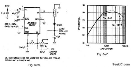
Figure 8-39 shows a MAX759 connected as an LCD-contrast supply with a -24-V output using an autotransformer. Figure 8-40 shows the efficiency curve. The MAX759 has a large lowJsaturation, internal P-channel MOSFET. The use of an autotransformer trades off higher peak switch currents for reduced stress voltage on the switch transistor. The circuit operates over a 4-V to 6-V range (with a maximum input/output differential of 30 V), draws 3.7-mA quiescent current, and is capable of 50-mA output. Mount L1 close to the IC to minimize PC-trace inductance in the LX lead. MAXIM BATTERY MANAGEMENT CIRCUIT COLLECTION, 1994, P. 47, 48.
(View)
View full Circuit Diagram | Comments | Reading(917)
METRONOME_Ⅱ
Published:2009/7/1 2:28:00 Author:May
This simple circuit uses a multivibrator to generate the beats and a subsequent audio amplifier stage to increase the output level. Range of adjustment is approximately from 40 to 200 beats per minute set by the gauged potentiometer. (View)
View full Circuit Diagram | Comments | Reading(698)
Stand_alone_LCD_contrast_bias_supply_digitally_adjusted
Published:2009/7/24 5:24:00 Author:Jessie
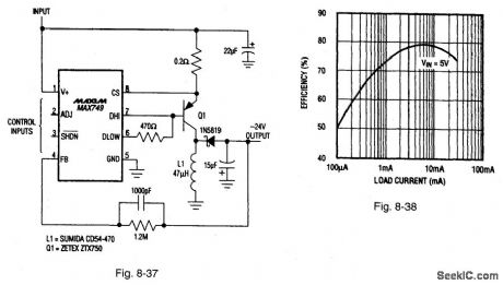
Figure 8-37 shows a MAX749 connected as an LCD-contrast supply with a digitally adjusted negative output. Figure 8-38 shows the efficiency curve. The MAX749 has an on-board five-bit D/A converter that adjusts the LCD contrast voltage (from 1/3 full-scale to full-scale) through a serial interface. No adjustment pots are needed, The circuit operates over a 2-V to 6-V range, draws 310-μA quiescent current, and is capable of 25-mA output. MAXIM BATTERY MANAGEMENT CIRCUIT COLLECTION, 1994, P. 46.
(View)
View full Circuit Diagram | Comments | Reading(789)
Continuous_output_sampled_bridge
Published:2009/7/24 5:23:00 Author:Jessie
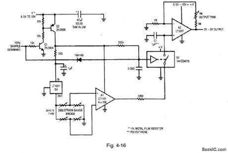
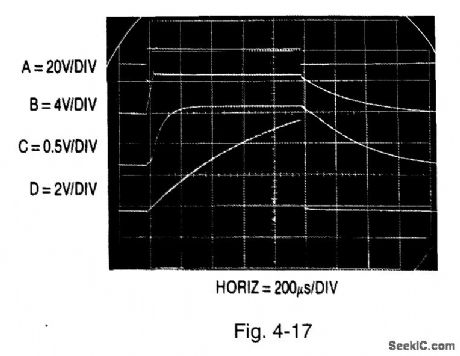
Figure 4-16 shows a bridge signal conditioner with sampled continuous output.Figure 4-17 shows the waveforms. Traces A, B, C, and D show the Q2 collector, LT1021-5 output, A1 output, and S1 input, respectively. The output is made continuous by the addition of a sample-hold stage. Q2 is off when the sample command is low. Under these conditions, only A2 and S1 receive power, resulting in a current drain of less than 60 μA. When the sample command is pulsed high, the Q2 collector (trace A, Fig. 4-17) goes high, providing power to all other circuit elements. During the sampling phase, supply current approaches 20 mA, but a 10-Hz sampling rate cuts effective drain below 250 μA. Slower sampling rates will further reduce drain, but the C1 droop rate (about 1 mV/100 ms) sets the accuracy constant. The 10-Hz rate provides adequate bandwidth for most transducers. For 3-mV/V-slope-factor transducers, the gain trim shown (1 M) allows proper calibration. It might be necessary to rescale the gain trim for other transducer types. The A2 output is accurate enough for 12-bit systems. Although the output is continuous, information is collected at a 10-Hz rate, and the Nyquist limit applies when interpreting the results. LINEAR TECHNOLOGY, APPLICATION NOTE 43, P. 21. (View)
View full Circuit Diagram | Comments | Reading(758)
AUDIO_FREQUENCY_METER
Published:2009/7/1 2:27:00 Author:May
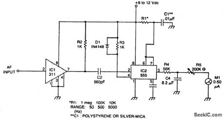
Circuit Notes
The meter uses time averaging to produce a direct current that is proportional to the frequency of the input signal. (View)
View full Circuit Diagram | Comments | Reading(0)
Combined_contrast_and_backlight_supply_for_LCD_displays
Published:2009/7/24 5:23:00 Author:Jessie
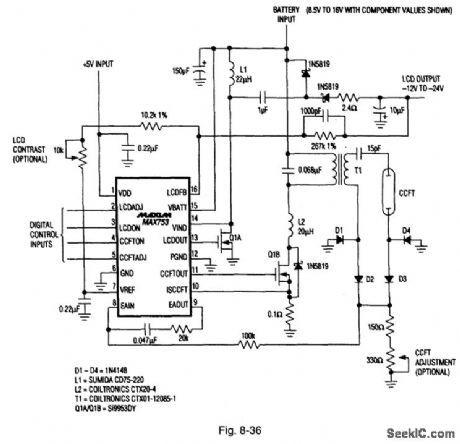
Figure 8-36 shows a MAX753 connected to provide both the contrast and backlight for LCD displays. The dc contrast voltage (-12 V to -24 V) is generated with a hybrid of boost regulator, plus Charge pump, under supervision of an on-board five-bit D/A converter, thus permitting microprocessor control of brightness. The circuit operates over a 6-V to 20-V range, draws 3-mA quiescent current, and is capable of 3-W output. MAXIM ENGINEERING JOURNAL, VOL. 3, 1994, P. 53.
(View)
View full Circuit Diagram | Comments | Reading(845)
AC_LINE_OPERATED_UNIJUNCTION_METRONOME
Published:2009/7/1 2:27:00 Author:May
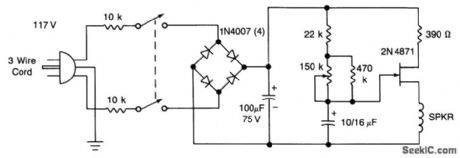
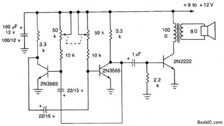
The UJT-oscillator frequency is determined by the 100μF capacitor and the effective resistance of the 22 K and 470 K resistors and the potentiometer. Rate can be varied from 42 to 208 beats/minute. The circuit should be housed in an insulated box for safety, or use ground (3-wire cord). (View)
View full Circuit Diagram | Comments | Reading(744)
CIRCUIT_FOR_MULTIPLYING_PULSE_WIDTHS
Published:2009/7/1 2:27:00 Author:May
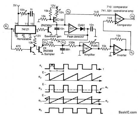
A circuit for multiplying the width of incoming pulses by a factor greater or less than unity is simple to build and has the feature that the multiplying factor can be selected by adjusting one potentiometer only. The multiplying factor is determined by setting the potentiometer P in the feedback of a 741 amplifier. The input pulses e1 of widthT and repetition period T is used to trigger a sawtooth generator at its rising edges to produce the waveform e2 having a peak value of (E) volt. This peak value is then sampled by the input pulses to generate the pulse train e3 having an average value of e4(=E ET/T) which is proportional to Tand independent on T. The dc voltage e4 is amplified by a factor k and compared with sawtooth waveform e4 giving output pulses of duration k T. The circuit is capable of operating over the frequency range 10 kHz - 100 kHz. (View)
View full Circuit Diagram | Comments | Reading(828)
Frequency_limit_detector
Published:2009/7/24 5:22:00 Author:Jessie
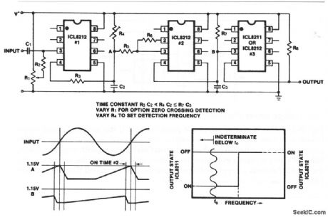
The first ICL8212 is used as a zero-crossing detector. The output circuit (R3, R4, C2) produces a slow positive ramp, where the negative range is much faster than the positive range, as shown. R5 and R6 provide hysteresis so that under all circumstances the second ICL8212 is turned on for sufficient time to discharge C3. The time constant of R7/C3 is much greater than for R4/C2.Depending on the desired output polarities for low and high input frequencies, either an ICL8211 or an ICL8212 can be used as the output driver. (View)
View full Circuit Diagram | Comments | Reading(1432)
PRECISION_REFERENCE_SQUARE_WAVE_VOLTAGE_REFERENCE
Published:2009/7/1 2:27:00 Author:May
View full Circuit Diagram | Comments | Reading(664)
Sampled_output_bridge_signal_conditioner
Published:2009/7/24 5:21:00 Author:Jessie
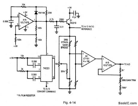
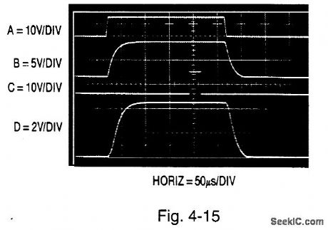
Figure 4-14 shows a bridge signal conditioner with sampled output. (This is an extension of the Fig. 4-13 circuit) Figure 4-15 shows the waveforms. Traces A, B, C, and D show the AIA output, Q1 emitter, 74C221 output, and A2 output, respectively. The strobing action is automated by a clocked sequence. Circuit on time is restricted to 250 μs, at a clock rate of about 2 Hz. This keeps average power consumption down to about 200 μA. Oscillator A1A produces a 250-μs clock pulse every 500 ms (trace A, Fig. 4-15). To calibrate, trim both zero and gain for the appropriate outputs. LINEAR TECHNOLOGY, APPLICATION NOTE 43, P. 20. (View)
View full Circuit Diagram | Comments | Reading(893)
High_supply_voltage_dump_circuit
Published:2009/7/24 5:21:00 Author:Jessie
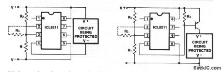
These circuits remove the power supply when there is a high-voltage overload. For circuits consuming less than 5 mA, the ICL8211 can drive the load directly. For higher load currents, a pnp or Darlington pair is required as shown. Resistors R1 and R2 set up the disconnect voltage, and R3 provides optional voltage hysteresis. (View)
View full Circuit Diagram | Comments | Reading(853)
POWER_LINE_FREQUENCY_METER
Published:2009/7/1 2:26:00 Author:May
Circuit Notes
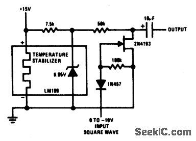
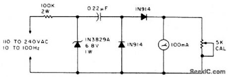
The meter will indicate the frequency from a power generator. Incoming sine waves are converted to square waves by the 100 K resistor and the 6.8 V zener. The square wave is differentiated by the capacitor and the current is averaged by the diodes. The average current is almost exactly proportional to the frequency and can be read directly on a 100 mA meter. To calibrate, hook the circuit up to a 60 Hz poweraline and adjust the 5 K pot to read 60 mA. (View)
View full Circuit Diagram | Comments | Reading(868)
CCFT_CCFL_backlight_supplies
Published:2009/7/24 5:21:00 Author:Jessie
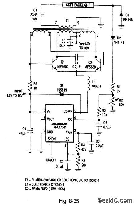
Figure 8-35 shows a MAX752 connected as a power supply for cold-cathode fluorescent tubes (CCFT or CCFL, whichever you prefer). CCFT/CCFLs require high-voltage aqpower, taken from a source that is not part of the main power supply. This is because the supply should be located physically close to the display (to prevent losses resulting from cable capacitance). Typically, the CCFT/CCFLs need about 2 W of 400-Vac power (that must reach near 1200 V upon startup) to arc and turn on the lamp. In this circuit, the MAX752 boost-regulator IC acts as a switching-regulator current source to feed the tail of a traditional Royer-type self-oscillating dc/dc converter. The Royer circuit drives a 33:1 transformer that steps up the battery voltage to ac high voltages (near 1200 V). Capacitance C2 and the primary inductance form a resonant circuit, which provides a low-EMI sine-wave drive signal to the lamp. A half-wave rectified signal proportional to tube current is returned to the MAX752 feedback input. This maintains the CCFT/CCFL current at a constant level. Display brightness is adjusted by R2. MAXIM ENGINEERING JOURNAL, Vot. 3, 1994, P. 51. (View)
View full Circuit Diagram | Comments | Reading(2099)
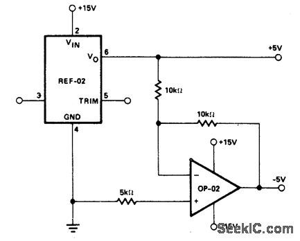
±_5_V_REFERENCE
Published:2009/7/1 2:26:00 Author:May
View full Circuit Diagram | Comments | Reading(600)
Strobed_power_strain_gauge_bridge
Published:2009/7/24 5:19:00 Author:Jessie
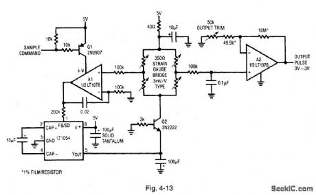
Figure 4-13 (derived from Fig. 4-6) shows a way to reduce power without sacrificing bridge signal-output level. The technique is applicable where continuous output is not a requirement. The circuit is in a quiescent state for long periods with relatively brief on times. (A typical application would be where remote weight information in storage tanks is sampled once per week.) Quiescent current is about 150 μA, with on-state current typically 50 mA. LINEAR TECHNOLOGY, APPLICATION NOTE 43, P. 19. (View)
View full Circuit Diagram | Comments | Reading(817)
METRONOME_I
Published:2009/7/1 2:26:00 Author:May
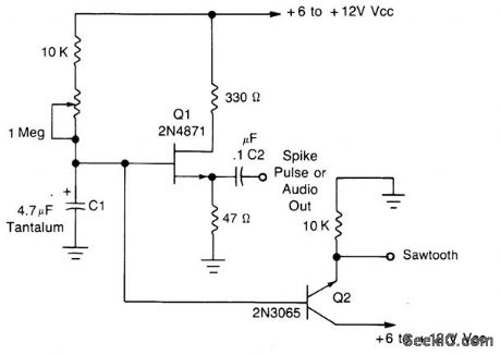
This simple oscillator uses a 2N4871 UJT to give pulses from 0.2 to about 20 Hz.A spike is available at C2, a sawtooth at the emitter of Q2 of about 2-3 V p-p, depending on VCC. (View)
View full Circuit Diagram | Comments | Reading(1184)
SIMPLE_METRONOME
Published:2009/7/1 2:25:00 Author:May
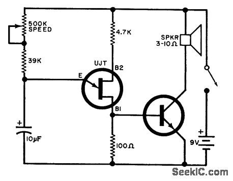
Adjustable from 15 to 240 beats per minute. The UJT oscillator output is applied to a general purpose npn transistor which drives the speaker.UJT=2N4871NPNxistor=TIP31 (View)
View full Circuit Diagram | Comments | Reading(2902)
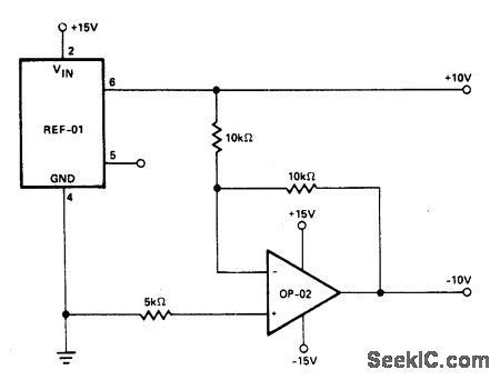
±_10_V_REFERENCE
Published:2009/7/1 2:25:00 Author:May
View full Circuit Diagram | Comments | Reading(594)
METAL_LOCATOR
Published:2009/7/1 2:24:00 Author:May
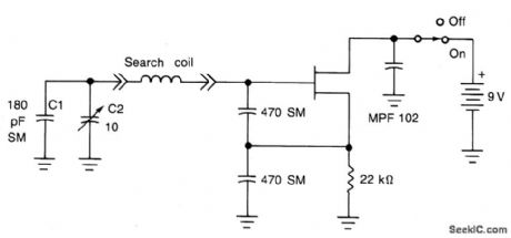
The search coil, C1 and C2 form a tuned circuit for the oscillator which is tuned near the center of the broadcast band. Tune a portable radio to a station near the middle of the band, then tune C2 until a squeal is heard as the two signals mix to produce a beat (heterodyne) note. Metal near the search coil will detune the circuit slightly, changing the pitch of the squeal. The search coil is 20 turns of number 30 enameled wire, wound on a 6 x 8 wood or plastic form. It is affixed at the end of a 30 to 40 wooden or plastic pole, and connected to the remainder of the metal detector circuit through a coaxial cable. (View)
View full Circuit Diagram | Comments | Reading(2006)
| Pages:1196/2234 At 2011811182118311841185118611871188118911901191119211931194119511961197119811991200Under 20 |
Circuit Categories
power supply circuit
Amplifier Circuit
Basic Circuit
LED and Light Circuit
Sensor Circuit
Signal Processing
Electrical Equipment Circuit
Control Circuit
Remote Control Circuit
A/D-D/A Converter Circuit
Audio Circuit
Measuring and Test Circuit
Communication Circuit
Computer-Related Circuit
555 Circuit
Automotive Circuit
Repairing Circuit