
Circuit Diagram
Index 1439
RELAY_INTERFACE_FOR_AMATEUR_RADIO_TRANSCEIVERS
Published:2009/6/16 23:05:00 Author:May
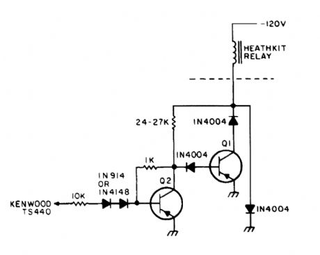
The relay power ln the linear IS obtained from the -120-V bias supply,and the transmit keving output from the Kenwood is+12 V at 10 mA maximum,The key ingredient in the circuit is the pnp driver transistor,which must be capable of handling at least 150 V at about 250 mA (View)
View full Circuit Diagram | Comments | Reading(810)
PROCESS_CONTROL_INTERFACE
Published:2009/6/16 23:02:00 Author:May

This circuit can be used to interface a 2-wire transmitter/sensor combination to an external de-vice or measurement setup. (View)
View full Circuit Diagram | Comments | Reading(700)
AUDIO_TO_ADC_INTERFACE
Published:2009/6/16 23:02:00 Author:May
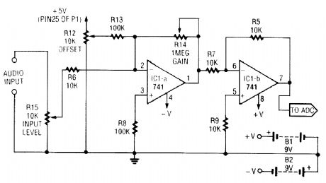
This simple general-purpose driver for an analog/digital converter uses two 741 IC devices with adjustable gain and offset. Other op amps might be substituted, but some circuit adjustments might beneeded. (View)
View full Circuit Diagram | Comments | Reading(3628)
TELEPHONE_INTERCOM
Published:2009/6/16 22:59:00 Author:May

An intercom using dual-modular wall jacks is shown in this circuit. If the wires are available in the home telephone cable, this system can be installed with little trouble. (View)
View full Circuit Diagram | Comments | Reading(1284)
VERY_SIMPLE_TELEPHONE_INTERCOM_CIRCUIT
Published:2009/6/16 22:58:00 Author:May
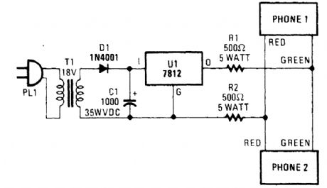
Tro telephones can be used as an intercom by using this circuit. Older style rotary phones that are nonelectronic might work best in this application. Also, handsets only might be powered this way. (View)
View full Circuit Diagram | Comments | Reading(3616)
ONE_WAY_VOICE_ACTIVATED_INTERCOM
Published:2009/6/16 22:57:00 Author:May
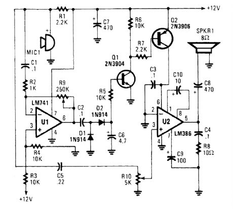
An omnidirectional electret microphone can be used to pick up the sound and convert it into an electrical signal. The output of the microphone is fed along two paths. In the first path, the signal is sent to the inverting input at pin 6. In the second path, the microphone signal is fed to the non-in-verting input of U2, where it is amplified and output to the speaker, SPKR1. (View)
View full Circuit Diagram | Comments | Reading(1338)
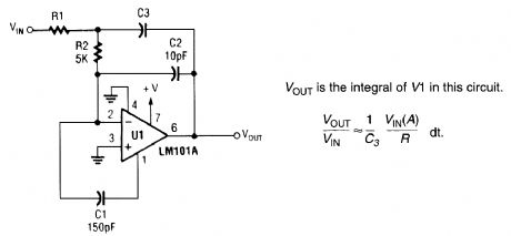
FAST_INTEGRATOR
Published:2009/6/16 22:54:00 Author:May
View full Circuit Diagram | Comments | Reading(1)
LM6218_HIGH_SPEED_INSTRUMENTATION_AMPLIFIER
Published:2009/6/16 22:53:00 Author:May
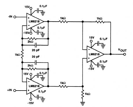
This amplifier features 400-μsec settling time (to 0.01%), 140-V/psec slow rate, and 17-MHz gain-bandwidth product. The supply voltage can be ±5 to ±20V. (View)
View full Circuit Diagram | Comments | Reading(693)
LMC6062_INSTRUMENTATION_AMPLIFIER
Published:2009/6/16 22:41:00 Author:May
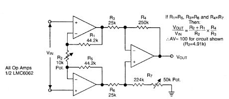
Useful for +5-V single-supply applications, this op amp circuit features low drain (around 1 mA), high input resistance (1014Ω), and low bias current (≈10-14A). (View)
View full Circuit Diagram | Comments | Reading(791)
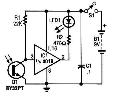
BI_COLOR_INDICATOR
Published:2009/6/16 22:36:00 Author:May
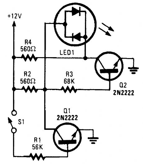
With S1 open, base bias is supplied to Q2 through avoltage divider (formed by R2 and R3), thus turning on the green element in the LED. That indicates that power is being supplied to the project.Ifyou close S1, current through RI biases Q1 on, thereby grounding the voltage divider and turning off Q2. That reverses the flow of current through the LED, which causes its red element to light. That indicates that the circuit is under power and S1 (really a DPDT switch), whose remaining section controls another circuit, is active. In this circuit, a bi-color LED is used to indicate when a circuit is under power and the status of S1. In that way, the LED does the job of two indicators. (View)
View full Circuit Diagram | Comments | Reading(1222)
POLARITY_INDICATOR
Published:2009/6/16 22:33:00 Author:May
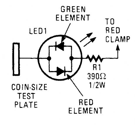
This circuit consists of a tri-color LED, a resistor, wire, and a coin-size test plate. You will have to build two such circuits-one for each black clamp on a set of auto battery jumper cables. The author installed the circuits inside the black clamps themselves using lengths of wire to make the connections to the red clamps.The first step is to connect one red clamp to what you believe is the positive post on the okay battery. Then, touch the test plate on the black clamp at the end of the cable to the negative termi-nal on the good battery. The LED will light red if the red clamp is on the wrong terminal. If so move the clamp to the other poJt and check again. If all is well, the LED will light green. Pick up the other black clamp and connect it to the remaining post on the good battery.Connect the remaining red clamp to what you assume to be the positive terminal on the bad battery. Now, touch the test plate on the remaining clamp to the engine block or a bare area on the dead car's frame. If the LED appears or doesn't glow, switch the red clamp to the other terminal and test again. When the LED glows green, attach the black clamp to the car's frame (which will prevent any sparks from occurring near the battery). When you remove the clamps, take the clamps off in reverse order to avoid sparks. (View)
View full Circuit Diagram | Comments | Reading(1)
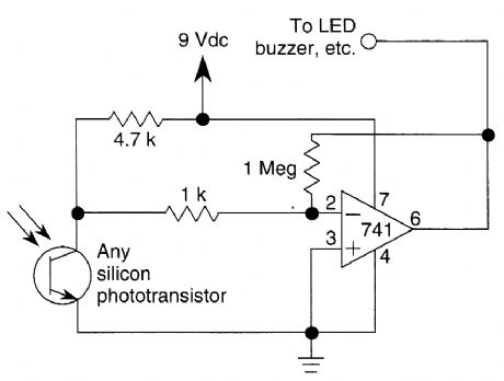
REMOTE_CONTROL_TESTER
Published:2009/6/16 22:28:00 Author:May
The IR Tester circuit lets you know if the but-ton you press on a remote control is working. Q1 is a photo transistor that is activated by IR energy. (View)
View full Circuit Diagram | Comments | Reading(1461)
IR_RECEIVER
Published:2009/6/16 22:26:00 Author:May
This circuitis just about the simplest IR ro-celver you can build The parts are cheap,the lay-outis not critical,and a 9-V battery will last a longtime (View)
View full Circuit Diagram | Comments | Reading(3)
VERY_SIMPLE_IR_REMOTE_CONTROL_CIRCUIT
Published:2009/6/16 22:25:00 Author:May
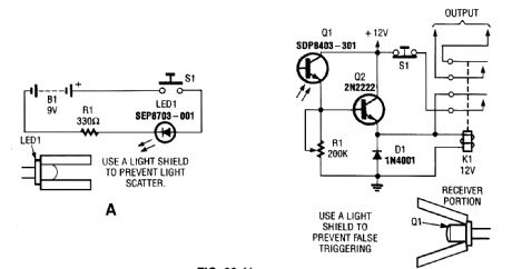
Here is a complete IR remote-control system that consists of a simple transmitter (A) and an equally simple receiver (B). (View)
View full Circuit Diagram | Comments | Reading(3037)
PULSED_INFRARED_TRANSMITTER_FOR_ON_OFF_CONTROL
Published:2009/6/16 22:21:00 Author:May
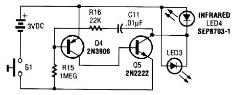
This transmitter consists of an oscillator and LEDs. It generates a pulsed tone of around 850 Hz. (View)
View full Circuit Diagram | Comments | Reading(681)
INFRARED_REMOTE_CONTROL_TESTER
Published:2009/6/16 22:20:00 Author:May
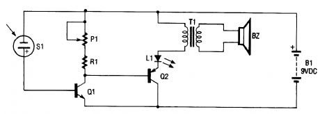
The infrared remote-control tester uses a sensitive PN-type solar sensor that is connected directly to a Darlington amplifier made up of transistors Q1 and Q2. Biasing is provided by RI and Pl, a variable resistor that serves as a sensitivity control. The collector lead of Q1 is the output lead of the Darlington amp, and it is connected to a red LED and the primary of transformer T1. The func-tion of T1 is to convert the low-voltage output signal to a level high enough to drive a small piezo disc.That disc makes a clicking sound when the sensor picks up an infrared signal that is varying in fre-quency or amplitude. The infrared sensor will also pick up visible light. The use of an IR filter (Wrat-ton #87) is recommended.
BZ Piezo DiscL1 Jumbo Red LEDP1 2-MΩ Trimmer Resistor Q1 2N3904 TransistorQ2 2N3906 TransistorR1 270-Ω ResistorS1 Solar SensorT1 Audio Transformer (View)
View full Circuit Diagram | Comments | Reading(3490)
WIRELESS_IR_HEADPHONE_RECEIVER
Published:2009/6/16 22:18:00 Author:May
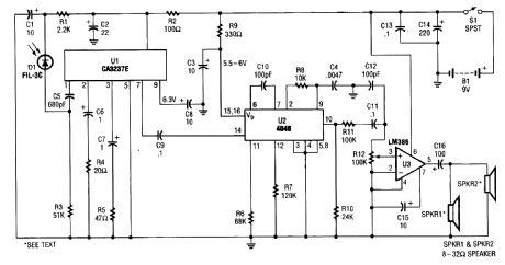
IR detector diode D1 intercepts the IR signal at around 40 kHz and feeds it from U1, a high-gain preamp, to PLL, U2, a 4046 configured to serve as an FM detector. U3 is an audio amplifier that feeds a pair of headphones or a speaker. (View)
View full Circuit Diagram | Comments | Reading(0)
WIRELESS_IR_HEADPHONE_TRANSMITTER
Published:2009/6/16 22:17:00 Author:May
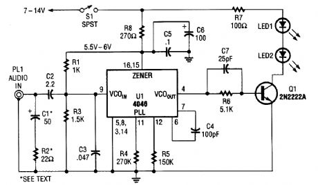


The transmitter for the wireless headphones is built around a CD4046 CMOS phase-locked loop, coupled with a driver transistor, and a pair of infrared LEDs. Although the CD4046 is comprised of two phase comparators, a voltage-controlled oscillator (or VCO), a source follower, and a zener ref-erence, only its VC0 is used in this application. (View)
View full Circuit Diagram | Comments | Reading(0)
SELECTIVE_PREAMPLIFIER_FOR_INFRARED_PHOTODIODE
Published:2009/6/16 22:15:00 Author:May
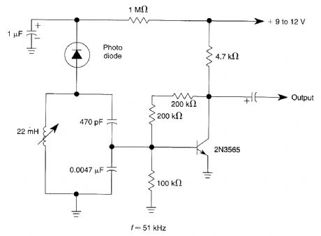
The circuit uses a tuned circuit to achieve frequency selection. Values are for operation at about 51 kHz. The 2N3565 amplifies the output developed by the tuned circuit. (View)
View full Circuit Diagram | Comments | Reading(1197)
INFRARED_RECEIVER
Published:2009/6/16 22:14:00 Author:May
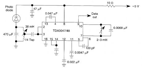
The circuit operates from a 5-V supply and has a current consumption of 2 mA. The output is a current source that drives or suppresses a current of more than 75 pA with a voltage swing of 4.5 V.The Q-killer circuit eliminates distortion of the output pulses because of the decay of the tuned in-put circuit at high input voltages. The input circuit is protected against signals of more than 600 mV by an input limiter. The typical input is an AM signal at a frequency of 36 kHz. (View)
View full Circuit Diagram | Comments | Reading(0)
| Pages:1439/2234 At 2014211422142314241425142614271428142914301431143214331434143514361437143814391440Under 20 |
Circuit Categories
power supply circuit
Amplifier Circuit
Basic Circuit
LED and Light Circuit
Sensor Circuit
Signal Processing
Electrical Equipment Circuit
Control Circuit
Remote Control Circuit
A/D-D/A Converter Circuit
Audio Circuit
Measuring and Test Circuit
Communication Circuit
Computer-Related Circuit
555 Circuit
Automotive Circuit
Repairing Circuit