
Circuit Diagram
Index 1436
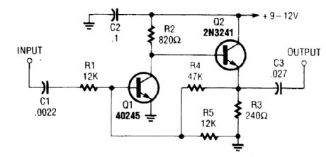
LOW_OFFSET_SIMPLE_VIDEO_BUFFER
Published:2009/6/17 2:13:00 Author:May
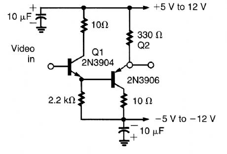
This circuit has proved to be an effective video buffer and will easily drive a 75-Ω load to 1.5-V p-p output. BW is better than 20 MHz and there is less than 0.05-V dc offset, which is the difference inVBE of Q1 and Q2. The supply lines should be well bypassed, ± 5V or more. (View)
View full Circuit Diagram | Comments | Reading(1418)
CMOS_TOUCH_DIMMER
Published:2009/6/17 2:13:00 Author:May
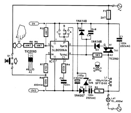
A Seimens SLB0586A IC allows the construction of a simple touch-controlled dimmer circuit.The circuit controls a triac ac switch,which allows control of loads from 10 to 400 W. (View)
View full Circuit Diagram | Comments | Reading(3326)
3_V_RAIL_TO_RAIL_SINGLE_SUPPLY_BUFFER
Published:2009/6/17 2:11:00 Author:May
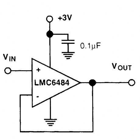
The LMC6484 provides a 3-V p-p rail-to-rail buffer with a +3-V supply commonly used for logic systems. (View)
View full Circuit Diagram | Comments | Reading(704)
MOS_LAMP_DRIVER
Published:2009/6/17 2:10:00 Author:May
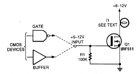
The circuit shows a way of using a MOSFET as a load driver. I1 can be a lamp, or any other load, that does not exceed the current rating of Q1. (View)
View full Circuit Diagram | Comments | Reading(848)
RUNNING_LIGHT_SEQUENCE_
Published:2009/6/17 2:10:00 Author:May

This running light sequencer drives 16 LEDs and runs from a 12-V supply. C1 can be varied to alter the rate of operation. (View)
View full Circuit Diagram | Comments | Reading(4912)
SIMPLE_VIDEO_BUFFER
Published:2009/6/17 2:10:00 Author:May

This simple emitter follower can be used as a video buffer. (View)
View full Circuit Diagram | Comments | Reading(4177)
MOSFET_BUFFER_AMPLIFIER
Published:2009/6/17 2:09:00 Author:May
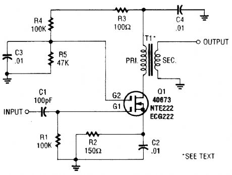
A MOSFET is used as a wideband buffer amplifier. T1 is wound on a toroid of approximately 1/2 diameter, with material suitable for frequency (usually 1- to 20-MHz range). The turns ratio should be about 4:1 depending on load imped-ance. Typically, at 4 MHz, there are 18 turns on the primary, 4 turns on the secondary, and the stage gain is about 14-dB voltage (ZL = 50 Ω). (View)
View full Circuit Diagram | Comments | Reading(1105)
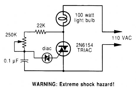
SIMPLE_TRIAC_CIRCUIT
Published:2009/6/17 2:08:00 Author:May
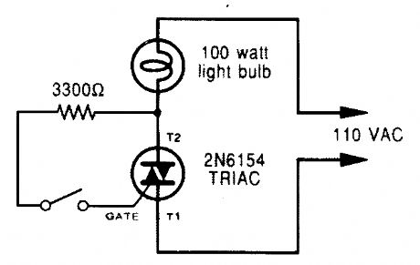
A triac can be used as a lirte-operated ac power switch that can directly control lamps, heaters, or motors. A brief and small current pulse into the gate turns the triac on; it remains on until the main current reverses. (View)
View full Circuit Diagram | Comments | Reading(1343)
100_dB_DYNAMIC_RANGE_LOG_GENERATOR
Published:2009/6/17 2:07:00 Author:May
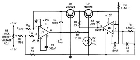
EOUT=constane×(LogEIN). This circuit has 100-dB dynamic range, which is five decades of voltage change at the input. (View)
View full Circuit Diagram | Comments | Reading(720)
120_ac_SHIMMERING_LIGHT
Published:2009/6/17 2:06:00 Author:May
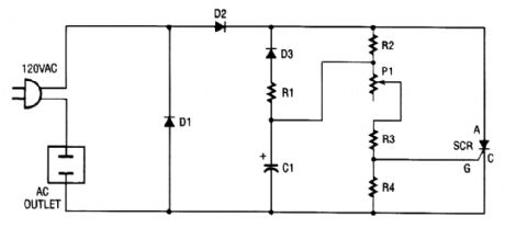
You can turn any ordinary household bulb into one that shimmers or blinks. This circuit works on any incandescent light up to 200 W, and runs on standard 120 Vac. The circuit uses an SCR to cause an ordinary lamp to shimmer. Note that one side of the lamp is connected directly to 120 Vac, and the other side of the lamp goes to the cathode of the SCR. As ac voltage is brought into the circuit through the line cord, it is full-wave rectified by diodes Dl and D2. That changes the ac to dc, and a portion of that dc voltage is applied to capacitor C1 through R2. Diode D3 blocks the (+) dc voltage so that only the voltage from the path of RI and D3 is clear. That forms an oscillator, which has a frequency de-termined by the setting of potentiometer PI (because the other components have fixed values).Remember to use extreme caution when using a device that connects to the ac line. Never use it outside or near water and always mount the entire kit inside a wooden or plastic (insulated) box to prevent any contact with the ac voltage. (View)
View full Circuit Diagram | Comments | Reading(946)
VFO_BUFFER_AMPLIFIER
Published:2009/6/17 2:06:00 Author:May
A two-transistor feedback pair provides broadband operation. The gain is approximately R4/R1. (View)
View full Circuit Diagram | Comments | Reading(1316)
PHASE_CONTROLLED_DIMMER
Published:2009/6/17 2:05:00 Author:May
A phase-controlled dimmer delays the triac VAC tum-on to a selected point in each successive ac half cycle. Use this circuit only for incandescent lamps, heaters, soldering irons, or “universal” motors that have brushes. (View)
View full Circuit Diagram | Comments | Reading(3)
THREE_POWER_LEVEL_TRIAC_CONTROLLER
Published:2009/6/17 2:04:00 Author:May
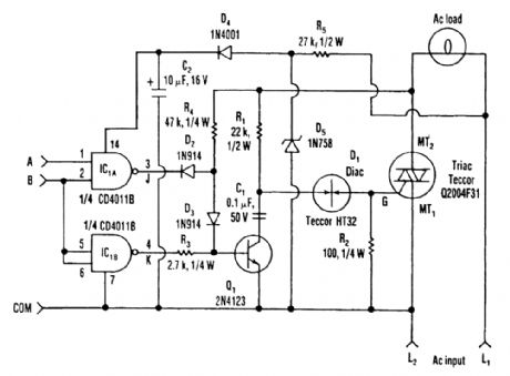
Three power levels are supplied by the two logic inputs of this enhanced circuit. R5, D4, D5, and C2 form a power supply for the logic IC. They can be omitted if another source of low voltage is available. (View)
View full Circuit Diagram | Comments | Reading(775)
HIGH_CURRENT_BUFFER
Published:2009/6/17 2:03:00 Author:May
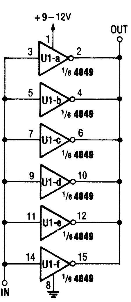
By parallel connecttng all six gates of this 4049 hex inverting buffer,you can obtain a much higher output current than would othewise be available. (View)
View full Circuit Diagram | Comments | Reading(1002)
DIMMER_FOR_LOW_VOLTAGE_LOADS
Published:2009/6/17 2:02:00 Author:May
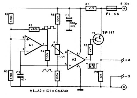
This circuit controls a low voltage dc supply by pulse width modulation. The switching rate is 200 Hz. Input supply voltage should be +5 to +30 V. Up to 5 A can be controlled. (View)
View full Circuit Diagram | Comments | Reading(718)
FUNCTION_GENERATOR
Published:2009/6/17 2:02:00 Author:May
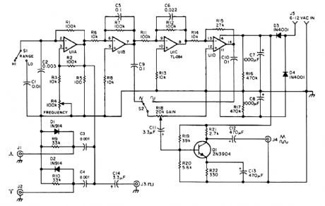

This function generator,based on an LT1016 high-speed comparator,will generate from a single +5V supply. The slow rate of the op amps used determines the maxlmum useable frequency of this circuit. (View)
View full Circuit Diagram | Comments | Reading(11)
AUTOMATIC_PORCH_LIGHT_CONTROL
Published:2009/6/17 2:01:00 Author:May
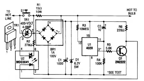
The automatic porch-light control circuit holds a triac on until a 4020 divider counts a number of 60-Hz powerline pulses. The circuit turns off a light after a predetermined time by using pins other than pin 3 of UI. Various times can be set. Consult the 4020 data sheet for information. (View)
View full Circuit Diagram | Comments | Reading(3552)
BUFFER_AMPLIFIERS
Published:2009/6/17 2:00:00 Author:May
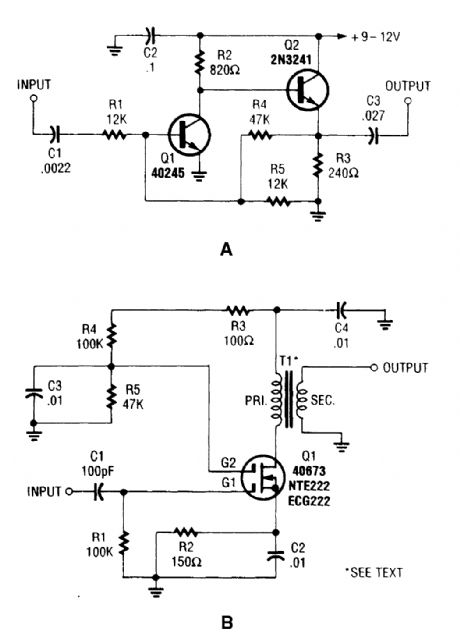
These two buffer/amplifiers that have been successfully used with VFOs: one (shown in A) is based on a pair of bipolar npn transistors, and the other (shown in B) is built around a dual-gate MOSFET. (View)
View full Circuit Diagram | Comments | Reading(891)
HOLIDAY_LIGHT_SEQUENCER
Published:2009/6/17 1:59:00 Author:May
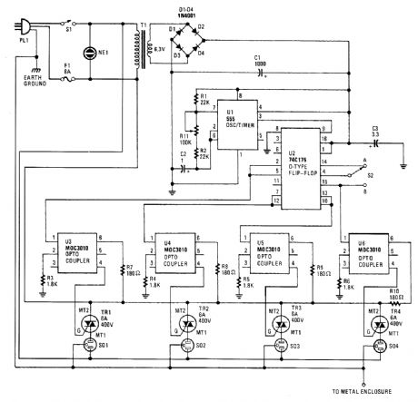
Integrated circuit UI (a 555 oscillator/timer) is wired as a conventional pulse generator. The fre-quency of the pulse generator is controlled by potentiometer R11. Resistor R2 puts a reasonable limit on the highest speed attainable.The output of the pulse generator is fed to the common clock input of U2, a 74C175 quad D-type flip-flop. Each flip-flop is configured so that its Q output is coupled to the D input of the subsequent flip-flop.Information on the D input of each flip-flop is transferred to the Q (and Q) outputs on the lead-ing edge of each clock pulse. Switch 52 allows you to invert the information on the D input of the first flip-flop at any time during the cycle. This allows you to create a number of different sequences, which are determined by the state of the CQ output at the time of the switching.Some of the possible sequences are:· 1 through 4 on, 1 through 4 off;· 1 of 4 on sequence;· 1 of 4 off sequence;· 2 of 4 on sequence;· 1 and 3 on to 2 and 4 off;· and other instances when the sequence of events is difficult to determine.However, if 52 is switched to position B while all outputs are high or all are low (which seldom occurs), the sequence stops and the outputs remain either all on or all off. If that happens, you only need to switch back to position A for at least one pulse duration, then back to position B again.Likewise, S2 should be in position A (pin 4 connected to pin 14) each time the power is turned on. This is because the data on pin 4 must be a logic 1 in order to start a sequence; otherwise all out-puts remain at logic 0, regardless of the clock pulses.Each output of the sequencing circuit is connected to an MOC3010 optoisolator/coupler (U3 through U6), which contains an infrared-emitting diode with an infrared-sensitive diac (triac driver or trigger) in close proximity. The diac triggers the triac, which carries the 117-volts ac.Each time that the infrared-emitting diode receives a logic 1, it turns on and causes the diac to conduct. With the o(Itoisolator/coup ler's internal diac conducting, the triac turns on, and power is supplied to whatever load is plugged into the corresponding ac socket. So, the sequencing circuit and the 117-V ac outputs are optically coupled and are effectively isolated from each other.Power for the sequencing circuit is provided by a 6.3-V miniature transformer. The output of the transformer is rectified by a four-diode bridge circuit, the output of which is filtered by C1 (1000-pF electrolytic capacitor). Capacitor C3 is added at the supply pin of U2 to suppress transients. (View)
View full Circuit Diagram | Comments | Reading(1837)
BARGRAPH_LED_BATTERY_TESTER
Published:2009/6/17 1:56:00 Author:May
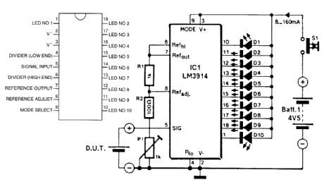
The LM3914A bargraph LED is used here as a voltmeter for battery testing. The circuit is pow-ered by a 4.5-V battery and compares the battery under test with an internally derived reference, set by R1/R2/P1. Each LED of the 10 represent 10% of full scale. For best results, the battery (D.U.T.) should be loaded with an appropriate resistor. (View)
View full Circuit Diagram | Comments | Reading(3170)
| Pages:1436/2234 At 2014211422142314241425142614271428142914301431143214331434143514361437143814391440Under 20 |
Circuit Categories
power supply circuit
Amplifier Circuit
Basic Circuit
LED and Light Circuit
Sensor Circuit
Signal Processing
Electrical Equipment Circuit
Control Circuit
Remote Control Circuit
A/D-D/A Converter Circuit
Audio Circuit
Measuring and Test Circuit
Communication Circuit
Computer-Related Circuit
555 Circuit
Automotive Circuit
Repairing Circuit