
Circuit Diagram
Index 1426
BROADBAND_RF_AMPLIFIER
Published:2009/6/17 23:19:00 Author:May
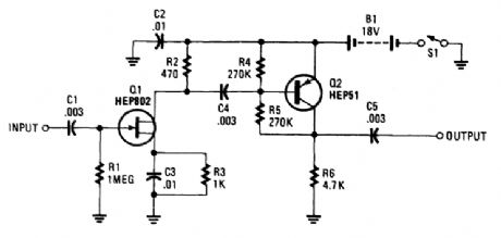
The use of a FET gives this amplifier a high input impedance. The bandwidth should be ade-quate for LW through HF use (dc-30 MHz), as an active antenna preamplifier. (View)
View full Circuit Diagram | Comments | Reading(3921)
BURGLAR_ALARM_CIRCUIT
Published:2009/6/17 23:18:00 Author:May
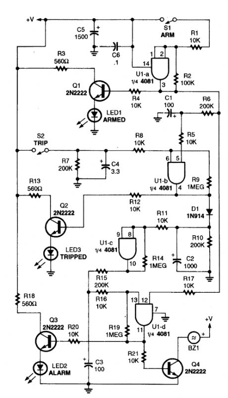
This alarm circuit is built around a single 4081 (CMOS) quad AND gate. It offers an exit and entry delay (around automatically reset two minutes after tripping, provided that the trip input is not left high).The arming switch must go high to arm or low to disarm. After arming, U1-a begins to charge C1 via R6. Around 20 seconds later (af-ter the exit delay), C1 has a sufficient charge to produce a high at the pin-5 input of UI-b.Also, when the circuit is armed, Q1 is turned on to indicate arming, and one input of U1-d is brought high.After the exit delay times out, if the trip in-put opens, it causes an output on gate U1-b.Transistor Q1 is turned on, lighting the trip indi-cator (LED3), C2 instantly charges, and the out-put of U1-c goes high. At that point, C3 begins charging to provide the entry delay.After 20 seconds, C3 has sufficient charge to produce a high at pin 13 of UI -d. That forces UI-d's output high, tuning Q3 and Q4 on, which activates the alarm indicator (LED2) and sounder (BZ1), respectively. If disarmed after a trip pulse, but before the 20-second, entry delay time out, pin 12 of U1-d goes low, so the gate's output does not go high and the alarm does not sound.Components C2 and RIO hold U1-c on for around 2 minutes and 20 seconds to provide the two-minute alarm. After C2's charge drops below half of the supply voltage, U1-c's output goes low, awaiting another trip pulse to set it off again. (View)
View full Circuit Diagram | Comments | Reading(0)
VHF_UHF_PREAMP_USING_MAR_x
Published:2009/6/17 23:17:00 Author:May
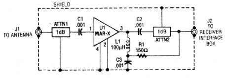
The MAR-x preamp shown will cover up to 1.5 or 2 GHz with the correct MAR-x IC. ATTN1 should be omitted for low noise-figure applications. ATTN1 and ATTN2 provide a means of lirniting possible termination range, for less chance of device instability. (View)
View full Circuit Diagram | Comments | Reading(793)
HF_PREAMPLIFIER
Published:2009/6/17 23:15:00 Author:May
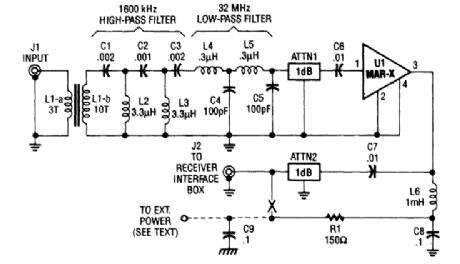
This HP SW receiver preamplifier is comprised of a broadband toroidal transformer (L1-a and L1-b), a complex LC network (comprised of a 1600-kHz, high-pass filter and a 32-MHz, low-pass fil-ter), L2 and L3 (26 turns of #26 enameled wire wound on an Amidon Associates T-50-2, red, toroidal core), a pair of resistive attenuators (ATTN1 and ATTN2), and of course, the MAR-x device. Exter-nal power for the preamp can be 9 to 12 Vdc. R1 can be increased in value for higher voltages. (View)
View full Circuit Diagram | Comments | Reading(1374)
AIR_FLOW_DETECTOR
Published:2009/6/17 23:14:00 Author:May
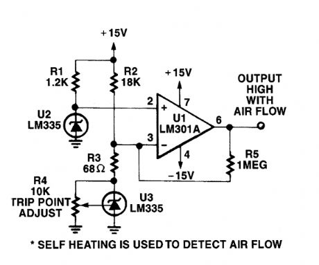
The self heating of a semiconductor that is cooled by airflow is used as a sensing method. (View)
View full Circuit Diagram | Comments | Reading(0)
ELECTRONIC_ANEMOMETER
Published:2009/6/17 23:11:00 Author:May
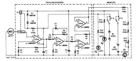
A motor used as a generator is used as a transducer to generate a dc voltage that is proportional to wind speed. K1 prevents the transducer voltages from being applied to the circuit if no dc power is present. UIA through UID is a dc amplifier, integrator, and buffer. This circuit drives the meter M1.The processor bqard is mounted in a housing along with the generator M1. (View)
View full Circuit Diagram | Comments | Reading(1576)
ULTRASONIC_REMOTE_CONTROL_RECEIVER
Published:2009/6/17 23:10:00 Author:May

A GC Electronics P/N J4-815 transducer is used to receive nals. The receiver drives a relay for control of another circuit. (View)
View full Circuit Diagram | Comments | Reading(922)
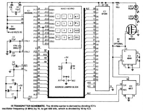
REMOTE_CONTROL_TRANSMITTER
Published:2009/6/17 23:07:00 Author:May

This transmitter can be used for a variety of purposes. An INS8048L microprocessor generates various codes depending on keypad presses. The codes are modulated on a 40-kHz carrier. Q1 drives IR LEDs LED1 and LED2. (View)
View full Circuit Diagram | Comments | Reading(1197)
HOT_WIRE_ANEMOMETER
Published:2009/6/17 23:07:00 Author:May
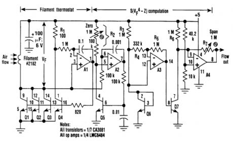
An anemometer can be realized by utilizing the inherent transconductance match of transistors in the array, instead of passive series resistances, to control filament current. As a result, as Al serves the collector current of Q4 and thereby the voltage across RI, it simultaneously adjusts the filantent (a 2182-type incandescent lamp denuded of its glass envelope) voltage, Vf. The ratio of the filament to RI current is stably maintained by the identical temperature and operating points of Q1 through Q4. The net result is that Al drives the filament temperature to the value that causes filament resis-tance to equal R1/3 = 33Ω. This is about double the cold resistance of the filament and therefore, as-suming tungsten wire with a 0.0045/degree coefficient of resistance, represents a filament operating temperature of around 230℃. This is hot enough that moderate changes in ambient temperature are unimportant factors in filament power demand, but not so hot as to cause the filament to burn.
Rail-to-rail input amplifier A2 continuously serves the collector current of Q5 to Vf/R2, making the Vbe of LQ5 a logarithmic function of Vf. A3 multiplies this log by 4 and applies the product of Q7.Q7 does the antilog function so that its collector current is proportional to the fourth power of Vf.Thus, by King's law, it's proportional to air speed in the vicinity of the filament. This current is offset and scaled by A4 to produce a voltage output that, thanks to the rail-to-rail output capability of the LMC6484, can range from 0.01 to 4.99 V Full-scale air speed can be adjusted, using R7, to any value in the range of 1 to 10 meters/s. (View)
View full Circuit Diagram | Comments | Reading(9)
ULTRASONIC_REMOTE_CONTROL_TRANSMITTER
Published:2009/6/17 23:04:00 Author:May
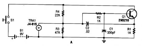
A GC Electronic P/N J4-815 ultrasonic transducer is used in this 40-kHz transmitter for remote-control application. (View)
View full Circuit Diagram | Comments | Reading(1178)
REMOTE_CONTROL_EXTENDER
Published:2009/6/17 23:03:00 Author:May
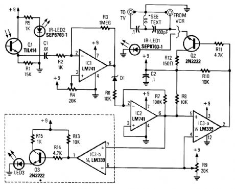
A signal from an IR remote control is converted from IR radiation to a frequency pulse that can be transmitted through coaxial TV cable or any other two-conductor wire to another room, where it's converted back into an IR signal. (View)
View full Circuit Diagram | Comments | Reading(1631)
AUDIO_LEVELER
Published:2009/6/17 22:56:00 Author:May
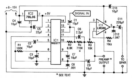
A low power programmable compandor chip, the Signetics NE577IC is used. Incoming audio is compressed, rectified and conditioned so that the input signal level always remains about the noise level. The compressor is an ALC circuit that outputs a constant level and the expander part of the IC is not used. (View)
View full Circuit Diagram | Comments | Reading(2861)
IF_AGO_NETWORK
Published:2009/6/17 22:56:00 Author:May
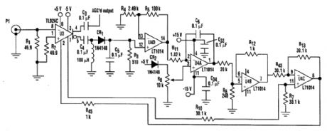
A simple IF AGC circuit that features wide dynamic range and excellent linearity can be achieved with two chips: Tl's TL026C voltage-controlled amplifier IC and Linear Technology's LT1014 (or any other similar basic quad op amp).
(View)
View full Circuit Diagram | Comments | Reading(1777)
INTERFACE_CIRCUITS_FOR_THE_REMOTE_CONTROL_TRANSMITTER
Published:2009/6/17 22:55:00 Author:May
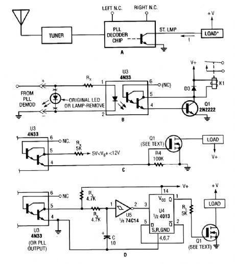
Shown here are several possible interface circuits that can be used with the remote-control transmitter. The one in A illustrates a typical FM stereo MUX decoder with a load connected directly to the open-collector output of a TA7343 PLL. The circuit in B illustrates an optoisolator-coupler out-put driving a 12-V relay coil via a general-purpose transistor. C shows the gate of an N-channel power MOSFET connected to the output of a 4N33. The final circuit, D, is a toggle flip-flop that allows push-on/push-off control. (View)
View full Circuit Diagram | Comments | Reading(2637)
REMOTE_CONTROL_RECEIVER
Published:2009/6/17 22:53:00 Author:May
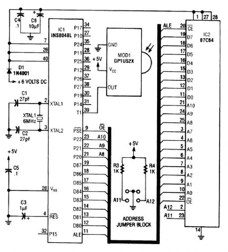
This circuit is based on the Sharp GP1U52X IR module and INS8048L microprocessor. The GP1U52X is a hybrid IC/infrared detector that provides a strong clean signal for later filtering and demodulation. (View)
View full Circuit Diagram | Comments | Reading(1391)
3_MHz_LOW_NOISE_AGO_SYSTEM
Published:2009/6/17 22:53:00 Author:May
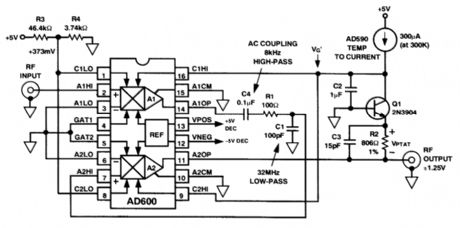
The AD600 dual voltage-controlled amplifier In this circuit provides a 3-MHz AGC system with80-dB range. (View)
View full Circuit Diagram | Comments | Reading(572)
AGC_AUDIO_PREAMP
Published:2009/6/17 22:52:00 Author:May
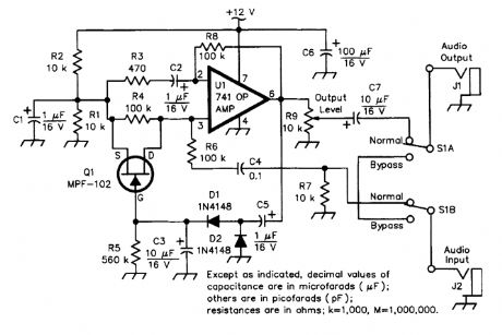


The circuit uses an easily obtained 741 op amp set for an internal gain of about 200. A portion of the op amp's output signal is rectified by the 1N4148 diodes, then filtered and fed to the gate of the FET input shunting circuit. As the output rises, more and more input shunting takes place. That is, more of the input signal is bypassed, effectively keeping the output level constant.The circuit offers a 100:1 limiting action. The input level can change over a 100:1 ratio with little or no effect on the output level. The output level itself can be set from less than unity all the way up to nearly the gain of the amplifier, making the circuit usable in other applications as well. (View)
View full Circuit Diagram | Comments | Reading(5526)
REMOTE_CONTROL_TRANSMIITER
Published:2009/6/17 22:49:00 Author:May
This transmitter sends an FM signal in the 88-to 108-MHz range, with a tone of 19 kHz. This can be used to activate the FM MPX pilot carrier indicator, which can be interfaced to external devices. L4 is for use with a 15 CM wire antenna. L1 is 9 turns of #26 enamelled wire on a 1/4-W 10-kΩ resistor (carbon type), L2 is 2 turns wound over L1. L3 is 7 turns of #26 enamelled wire on a 10-kΩ 1/4-W resistor. (View)
View full Circuit Diagram | Comments | Reading(1454)
SENSOR_ACTIVATED_RELAY_PULSER
Published:2009/6/17 22:46:00 Author:May
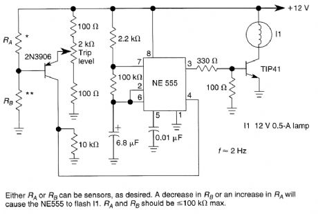
A sensor turns on Q1 to activate the low-frequency 555 oscillator, which pulses LAMP I1. Sensor may be sensitive to changes in light or temperature. (View)
View full Circuit Diagram | Comments | Reading(776)
TIME_DELAY_RELAY_
Published:2009/6/17 22:45:00 Author:May
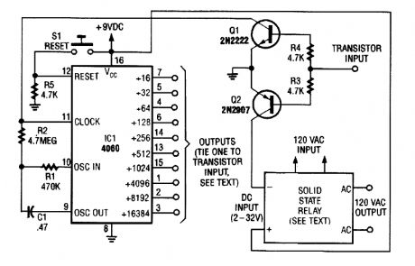
Using a 4060 CMOS binary divider and built-in clock oscillator, a long-duration timer can be made very simply. The solid-state relay can be sized for your application, and can be replaced with a mechanical relay if a suitable power supply is available. With the components shown, a 4.5-Hz clock frequency is generated. Divided outputs are available from÷ 4 to 16384 (about 4 hours). (View)
View full Circuit Diagram | Comments | Reading(5003)
| Pages:1426/2234 At 2014211422142314241425142614271428142914301431143214331434143514361437143814391440Under 20 |
Circuit Categories
power supply circuit
Amplifier Circuit
Basic Circuit
LED and Light Circuit
Sensor Circuit
Signal Processing
Electrical Equipment Circuit
Control Circuit
Remote Control Circuit
A/D-D/A Converter Circuit
Audio Circuit
Measuring and Test Circuit
Communication Circuit
Computer-Related Circuit
555 Circuit
Automotive Circuit
Repairing Circuit