
Circuit Diagram
Index 1427
SOLID_STATE_RELAY_CIRCUITS
Published:2009/6/17 22:41:00 Author:May
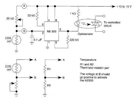
This dark-activated relay switch can be used to turn on walkway or other outdoor lighting at dusk. By using alternate connections to A and B, increasing illumination, high and low temperatures can be sensed. (View)
View full Circuit Diagram | Comments | Reading(1280)
SOLID_STATE_RELAY_CIRCUIT
Published:2009/6/17 22:39:00 Author:May
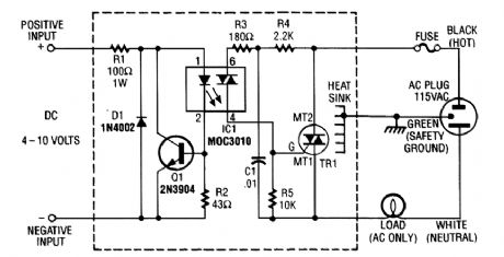
R1 limits input current while Q1 acts as a current sink to protect IC1. D1 serves as a polarity pro-tector. IC1 provides a trihc output to trigger the main triac, TR1. (View)
View full Circuit Diagram | Comments | Reading(2122)
SOLID_STATE_LATCHING_RELAY
Published:2009/6/17 22:38:00 Author:May
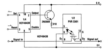
This simple circuit provides a solid-state equivalent of the electromechanical latching relay (see the figure). What's more, the switching is clean, highly resistant to vibration and shock, and isn't sen-sitive to magnetic fields or position.The circuit operates as follows: a set pulse to the 4043 RS latch takes its output high and turn on the 2N3904 transistor. Current will then flow through the photovoltaic relay's LED and the resistance between D1 and D2 will fall from several gigaohms to less than 30 Ω. The PVR will remain in this state until a reset pulse is received by the 4043 RS latch. (View)
View full Circuit Diagram | Comments | Reading(2019)
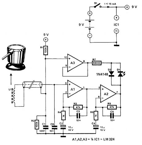
METAL_LOCATOR
Published:2009/6/17 22:34:00 Author:May
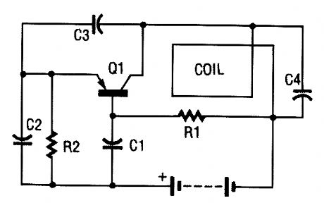
The metal locator uses a one-transistor oscillator and an AM radio to detect metal. Transistor Q1 is a pnp transistor that is connected to an oscillator. Resistor RI provides the correct base bias and capacitors C3 and C4 and the search coil determine the frequency of oscillation.Capacitors C3 and C4 are fixed in value, but the search coil is an inductor that varies in induc-tance (and thus varies the oscillator frequency) as metal is brought near it. The oscillator frequency is rich in harmonics and its output falls within the AM broadcast band. The metal detector works by combining its output with the local oscillator of the AM radio. The resulting net output of the radio is a low-frequency audio tone that changes-gets higher or lower-as metal is brought near or taken away from the search coil. Commercial metal detectors use two oscillators, so they don't require an AM radio. This metal locator provides an inexpensive alternative to an expensive commercial metal locator.
C1,C2 0.01-μF Capacitor (103)C3,C4 0.001-μF CapacitorQ1 2N3906 TransistorR1 47-kΩ ResistorR2 100-Ω Resistor (View)
View full Circuit Diagram | Comments | Reading(1)
NE6O2_SUPERHET_FRONT_END
Published:2009/6/17 22:34:00 Author:May
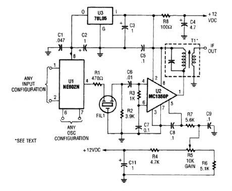
By using an NE602 with a filter and an MC1350P IC, a front end and an IF system for a basic su-perheterodyne receiver can be built with few parts. T is any suitable IF transformer for 262 kHz, 455 kHz, 10.7 MHz, etc. (View)
View full Circuit Diagram | Comments | Reading(2114)
LOW_COST_METAL_DETECTOR_FOR_EXPERIMENTERS
Published:2009/6/17 22:33:00 Author:May
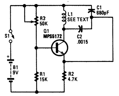
This circuit is on oscillator with L1 being a 4 diameter coil of 35 turns of #26 magnet wire.Metal in proximity to L1 will cause the oscillator to shift frequency. An AM transistor radio is used to detect the frequency shift. (View)
View full Circuit Diagram | Comments | Reading(916)
METAL_PIPE_DETECTOR
Published:2009/6/17 22:32:00 Author:May
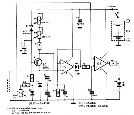
This circuit uses a 15-kHz oscillator coil. When metal placed in the energy field is withdrawn, the oscillator voltage is rectified and compared to a reference. A drop in oscillator voltage therefore op-erates comparator IC2 and D4 (LED) extinguishes. (View)
View full Circuit Diagram | Comments | Reading(1231)
TRANSISTORIZED_AM_RADIO
Published:2009/6/17 22:32:00 Author:May
Shown is a schematic of a typical transistor AM radio. This circuit uses npn transistors. The circuit is generic; therefore, no specific values are given for some components. This circuit is for ref-erence, to serve as a starting point for experimenters. (View)
View full Circuit Diagram | Comments | Reading(4648)
SUPER_SIMPLE_SHORTWAVE_RECEIVER
Published:2009/6/17 22:31:00 Author:May
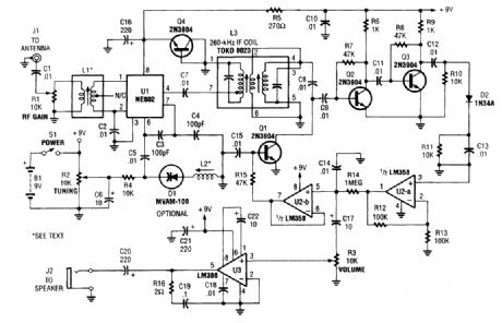
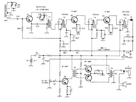
Integrated circuit U1 (an NE602 double-balanced mixer) is a combination oscillator and frequency mixer. Signals from the antenna input (at J1) are fed through dc-blocking capacitor C1 to the RF-gain control, R1, and fed to the input of U1 at pins 1 and 2.The local-oscillator frequency, which varies with the settings of R2 and L2, is mixed internally within U1, resulting in an output. The ntixer output at pin 4 of U1 is applied to a tunable 260-kHz band-pass intermediate-frequency (IF) transformer, L3, through dc-blocking capacitor C7. There-fore, signals that are roughly 260 kHz above and below the local-oscillator frequency are passed while others are effectively blocked. The IF frequencies are now amplified by Q2 and Q3. The AM au-dio signal is detected by D2 and its associated components, which bypass the RE signals, and leave only the audio signals. The signals are preamplified by U1-a (half of an LM358 dual op amp). The audio is then boosted to speaker level by the LM386low-voltage audio power amplifier, U3. (View)
View full Circuit Diagram | Comments | Reading(5349)
ZENER_DIODE_TEST_SET
Published:2009/6/17 22:30:00 Author:May
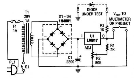
This versatile circuit can be used to test zener diodes or act as a stand-alone power supply. It re-quires a voltmeter to work as a zener tester. (View)
View full Circuit Diagram | Comments | Reading(4606)
AUDIO_FREQUENCY_METER_CIRCUIT
Published:2009/6/17 22:30:00 Author:May
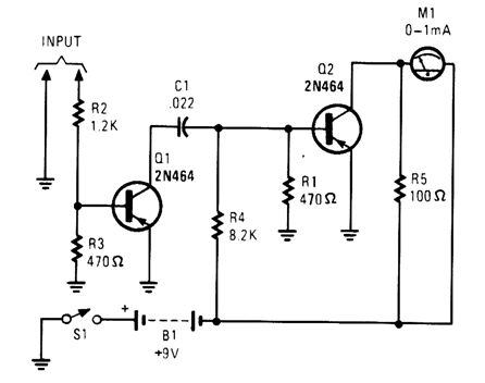
This simple tachometer circuit uses a pulse shaper Q1 to drive M1, a 0- to 1-μA meter. C1 can be varied to optimize operation. (View)
View full Circuit Diagram | Comments | Reading(882)
SUPPLY_VOLTAGE_MONITOR
Published:2009/6/17 22:29:00 Author:May
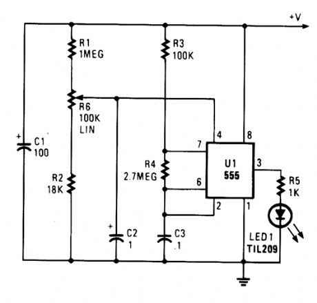
Excessive voltage causes U1 to oscillate, causing LED1 to flash. R6 sets the desired trip level. (View)
View full Circuit Diagram | Comments | Reading(672)
CONTINUITY_TESTER_FOR_LOW_RESISTANCE_CIRCUITS
Published:2009/6/17 22:28:00 Author:May
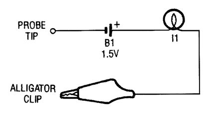
The continuity tester is little more than a battery and a lamp connected in series, with one end of the string terminated in an alligator clip, and the other end connected to the probe tip. (View)
View full Circuit Diagram | Comments | Reading(1845)
CHECK_FOR_op_AMP_dc_OFFSET_SHIFT
Published:2009/6/17 22:28:00 Author:May

The dc values of op-amp offsets can't always be taken for granted when delivering ac outputs. No device is ever exactly symmetrical for maximum positive slew rate versus maximum negative slew rate. Consequently, there is always some range of output slew rates in which the device used limits in one direction more severely than in the other. What results in rectification of the ac signal and an apparent shift of the dc offset.This test circuit can check for the shift phenomenon. The accompanying table and graph illus-trate the results obtained for four devices, all of different types. As frequency and slew rate are in-creased, the effect can be either relatively abrupt (LF412CN and NE55532N) or relatively gradual (LF358J and TL082CP). (View)
View full Circuit Diagram | Comments | Reading(1337)
JFET_VOLTMETER
Published:2009/6/17 22:26:00 Author:May
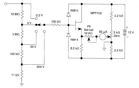
This very simple voltmeter circuit uses a 50-pA meter in a bridge circuit. It is useful for noncrit-ical applications. (View)
View full Circuit Diagram | Comments | Reading(874)
ac_OUTLET_TESTER
Published:2009/6/17 22:25:00 Author:May
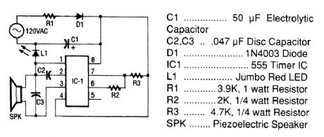
The tester consists of a rectifier circuit and a multivibrator circuit. The ac voltage is half-wave rectified by diode D1 and stored in capacitor C1. Resistor R1 is used to limit the current through D1 to a safe value. The voltage stored across C1 supplies IC1 operating powen The IC, the versatile 555 timer, is configured to operate as a multivibration whose operating frequency is determined by C2, R2, and R3. The output of IC1, on pin 3, is coupled to a piezoelectric speaker (SPK), which gives an indication of the presence of ac. An LED (L1) also lights when ac is present. (View)
View full Circuit Diagram | Comments | Reading(889)
AUDIBLE_CONTINUITY_TESTER
Published:2009/6/17 22:25:00 Author:May
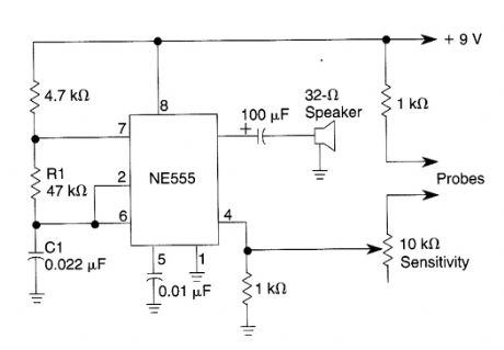
This 555 oscillator sounds a tone when continuity exists between the probes. Oscillator frequency is deterrrtined by the values of R1 and C1. (View)
View full Circuit Diagram | Comments | Reading(1)
ac_WIRING_LOCATOR
Published:2009/6/17 22:24:00 Author:May
This circuit uses a pick-up coil to sense the 50-or 60-Hz field around telephone pick-up coil with a suction pad. D1 (LED) lights during positive ac current is present. (View)
View full Circuit Diagram | Comments | Reading(1072)
DEBOUNCE_CIRCUIT
Published:2009/6/17 22:23:00 Author:May
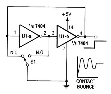
This debounce circuit will keep the electrical noise generated by the mechanical switch (S1) from reaching the next circuit in line. (View)
View full Circuit Diagram | Comments | Reading(1233)
LINEAR_INDUCTANCE_METER
Published:2009/6/17 22:22:00 Author:May
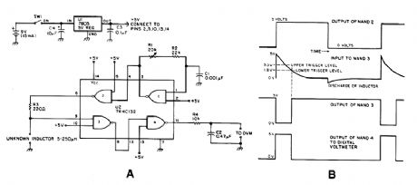
Using the fact that in an RL circuit, the pulse width seen across the inductor is proportional to the inductance, this circuit reads this indirectly on a DVM. The range is about 5 to 250 μH. (View)
View full Circuit Diagram | Comments | Reading(1032)
| Pages:1427/2234 At 2014211422142314241425142614271428142914301431143214331434143514361437143814391440Under 20 |
Circuit Categories
power supply circuit
Amplifier Circuit
Basic Circuit
LED and Light Circuit
Sensor Circuit
Signal Processing
Electrical Equipment Circuit
Control Circuit
Remote Control Circuit
A/D-D/A Converter Circuit
Audio Circuit
Measuring and Test Circuit
Communication Circuit
Computer-Related Circuit
555 Circuit
Automotive Circuit
Repairing Circuit