
Circuit Diagram
Index 1425
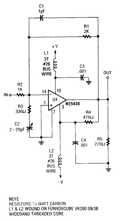
UHF_AMPLIFIER
Published:2009/6/18 1:55:00 Author:May
View full Circuit Diagram | Comments | Reading(732)
SIMPLE_455_kHz_IF_AMPLIFIER
Published:2009/6/18 1:54:00 Author:May

The ZN416E can be configured as a simple 455-kHz IF amplifier. In this case, the drcuit's center frequency and bandwidth are set by RES1 (a Murata CSB455E ceramic resonator). (View)
View full Circuit Diagram | Comments | Reading(3158)
20_W_1296_MHz_AMPLIFIER_MODULE
Published:2009/6/18 1:53:00 Author:May
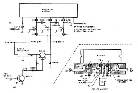
Using a Mitsubishi M57762 amplifier module, this amplifier delivers 20-W output on 1296 MHz. A single 12-V nominal power supply can be used. (View)
View full Circuit Diagram | Comments | Reading(3487)
RECEIVER_SCANNER_PREAMP_USING_MAR_1_MMIC
Published:2009/6/18 1:50:00 Author:May
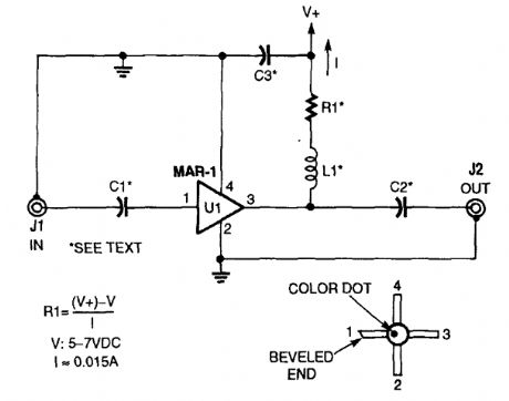
The low-cost Mini-Circuits MAR-X series of chips offer the RF builder a real advantage, with their inherent 50-Ω input and output impedances (needed for RF systems). An MAR-l-based re-ceiver/scanner preamplifier is shown. C1 and C2 are chip capacitors. Use 0.01 μF for HF, 0.001 for VHF, and 100 pF for above 100 MHz, depending on the low-frequency limit that you desire. C3 can be a ceramic disc of 0.01 μF or 0.001 μF, de-pending on frequency range. L1 is an RF choke that is suitable for the frequency range that you desire (0.1 to 10 μH). (View)
View full Circuit Diagram | Comments | Reading(2581)
2_METER_FET_POWER_AMPLIFIER_FOR_HTs
Published:2009/6/18 1:48:00 Author:May
Using a power MOSFET, this amplifier can boast a 2-W handie-talkie power level to around 10 W on 2 meters. A transmission-line RE switch is used for T/R switching. (View)
View full Circuit Diagram | Comments | Reading(1069)
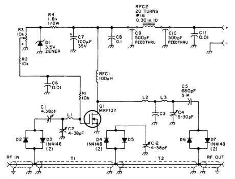
10_W_10_METER_LINEAR_AMPLIFIER
Published:2009/6/18 1:45:00 Author:May
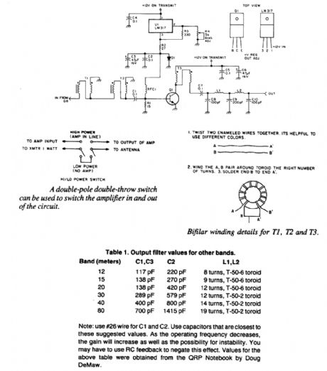
This linear amplifier delivers 10-W PEP output with 1.25-W drive on 10 m. T1, T2, and T3 are 10 turns of bifilar windings on an FT-50-43 toroidal core. The transformers are broadband. Filters for other bands, if desired, are shown. (View)
View full Circuit Diagram | Comments | Reading(1134)
TV_SOUND_SYSTEM
Published:2009/6/18 1:43:00 Author:May
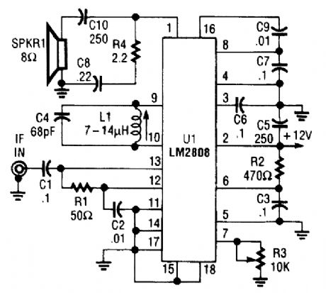
An LM2808 performs IF amplification of the 4.5-MHz sound subcarrier, limiting, detection, and audio amplification. If the center frequency must be changed, then change L1/C4. Audio out-put is 0.5 W. R3 is the volume control. (View)
View full Circuit Diagram | Comments | Reading(758)
WIDEBAND_POWER_AMPLIFIER
Published:2009/6/18 1:43:00 Author:May
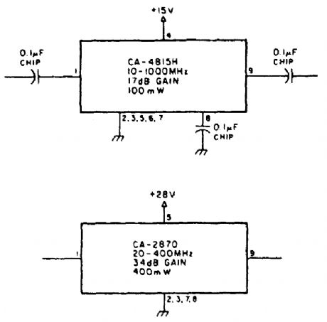
Using TRW P/N CA-815H, a 17-dB gain am-plifier that delivers 100 mW over 10 to 1000 MHz can be constructed. The CA-2870 will yield 0.4 W with 34-dB gain from 20 to 400 MHz. (View)
View full Circuit Diagram | Comments | Reading(810)
20_W_450_MHz_AMPLIFIER
Published:2009/6/18 1:41:00 Author:May
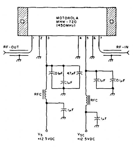
Delivering 20-W output, this amplifier has a gain of 21 dB at 450 MHz. A 12-V supply powers this circuit. (View)
View full Circuit Diagram | Comments | Reading(777)
30_MHz_AMPLIFIER
Published:2009/6/18 1:40:00 Author:May
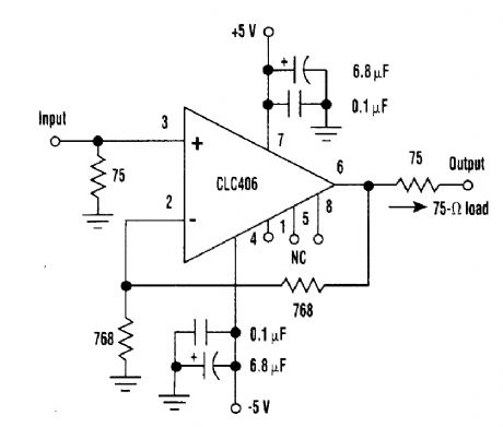
Using a CLC406 op amp, this video amplifier has a voltage gain of +2 and is flat to 30 MHz. The circuit should be useable in video switching and interfacing applications. (View)
View full Circuit Diagram | Comments | Reading(788)
MINIATURE_WIDEBAND_AMPLIFIER
Published:2009/6/17 23:39:00 Author:May

Except for the coupling and decoupling capacitors, IC1 is a complete wideband amplifier that has a fixed gain of 20 dB to 450 MHz. No external compensation is required. (View)
View full Circuit Diagram | Comments | Reading(1213)
70_MHz_RF_POWER_AMPLIFIER
Published:2009/6/17 23:38:00 Author:May
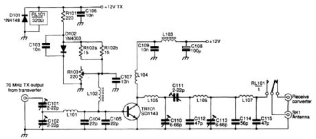
The SD1143 transistor provides a gain of about 14 dB in this circuit. It uses the fact that a 175-MHz device has a much higher gain when used at lower frequencies. The amplifier was originally de-signed to be used with a transverter. The output is 8 to 10 W for a 300- to 500-mW input. (View)
View full Circuit Diagram | Comments | Reading(1397)
BROADCAST_BAND_RF_AMPLIFIER
Published:2009/6/17 23:36:00 Author:May
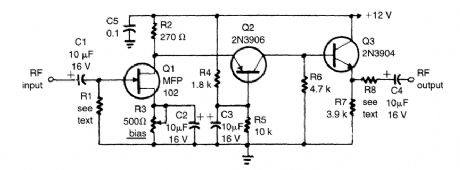
The circuit has a frequency response that ranges from lO0 Hz to 3 MHz; the gain is about 30 dB. Field-effect transistor Q1 is configured in the common-source self-biased mode; optional resistor R1 allows you to set the input impedance to any desired value. Commonly, it will be 50 Ω. The signal is then direct-coupled to Q2, a common-base circuit that isolates the input and output stages and pro-vides the amplifier's exceptional stability. Last, Q3 functions as an emitter-follower, to provide low output impedance (about 50 Ω). If you need higher output impedance, include resistor R8. It will af-fect impedance according to this formula:R8≈ROUT - 50. Otherwise, connect output capacitor C4 directly to the emitter of Q3. (View)
View full Circuit Diagram | Comments | Reading(0)
MOTORCYCLE_ALARM
Published:2009/6/17 23:34:00 Author:May
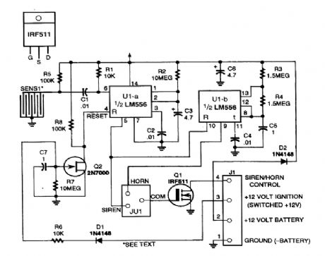
A dual tinter is used to generate a long pulse, which gates a second timer, producing a square wave (nonsymmetrical) and controls the on/off time of the hom. Siren operation can be selected with a jumper. In this case, the output of Q1 will be continuously on and not cycled. Sensor S1 is a row of adjacent circuit board traces with a stainless steel ball bearing laying on them. Any movement causes momentary shorting and opening of the circuit, triggering U1-a. (View)
View full Circuit Diagram | Comments | Reading(155)
CAR_ALARM_DECOY
Published:2009/6/17 23:32:00 Author:May
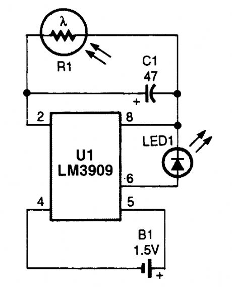
The device will simulate the presence of a burglar alarm in automobiles or homes. Mount RI where daylight can fall on it. During darkness, LED1 flashes, making potential intruders think an alarm system is installed. (View)
View full Circuit Diagram | Comments | Reading(911)
FLASHING_BRAKE_LIGHT_FOR_MOTORCYCLES
Published:2009/6/17 23:31:00 Author:May
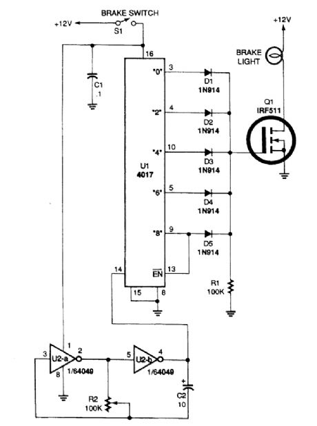
When brake-light switch 51 is closed, power is applied to UI and U2. Two inverters of U2, a 4049 hex inverting buffer, are connected in a low-frequency oscillator circuit that feeds clock pulses into UI, a 4017 decade counter/divider. Outputs 0, 2, 4, 6, and 8 of U1 are coupled to the gate of Ql through a 1N914 diode. As the 4017 counts down, it turns the brake light on and offfour times and then leaves it on until the brake switch is released. The on/off rate can be set by potentiometer R2; for best results, the on/off rate should be set so that it is rapid. (View)
View full Circuit Diagram | Comments | Reading(1334)
AUTO_SECURITY_SYSTEM_RECEIVER
Published:2009/6/17 23:28:00 Author:May
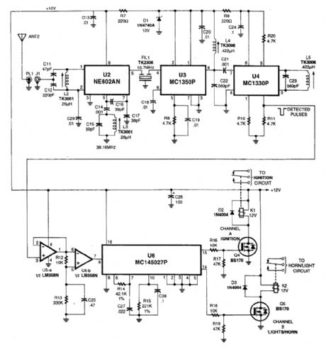
This receiver is a superheterodyne type tuned to 49 MHz. U2 is a mixer, followed by a 10.7-MHz filter and two-stage IF (U3, U4) and detector. The encoded received RE pulse signal from the an-tenna produces detected pulse from the MC1330P. These pulses are arrtplified by U5 and fed to de-coder IC U6, and MC1450278. Two channels are available at the output, which drives K1 and K2.
(View)
View full Circuit Diagram | Comments | Reading(2011)
HOME_SECURITY_SYSTEM
Published:2009/6/17 23:25:00 Author:May
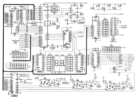
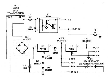
At the heart of the main-control unit is U16, Zilog's Z8-8-bit microcontroller, which receives its program instruction from U17, a 27C64 8K x 8 EPROM. The home security system in its most basic form, features eight individual protection zones, adjustable entry and exit delays, a panic switch (for emergency situations), automatic system reset, support for an auto-dialer (which, in case of emergency, dials pre-programmed telephone numbers), it's X-10 compatible (allowing it to control house lights and ap-pliances), has a backup battery (to keep the system on-line during a power failure), and there is also an optional zone-status panel that is used to individually show the condition of each protection zone.This system's power supply provides 12 Vdc for the sirens and digital keypad, and 5 Vdc for the on-board electronics, while also providing a constant 12-V output that's used to charge the backup-battery. (View)
View full Circuit Diagram | Comments | Reading(32)
LOW_NOSIE_GASFET_PREAMP_FOR_435_MHz
Published:2009/6/17 23:21:00 Author:May
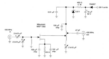
This circuit is a low-noise preamplifier for the 435-MHz amateur satellite frequencies. The cir-cuit uses a Mitsubishi MGF1302. A 28-Vdc source is shown, although by changing the 400-Ω 5-W re-sistor lower voltages can be used. (View)
View full Circuit Diagram | Comments | Reading(1766)
AUTO_SECURITY_SYSTEM_TRANSMITTER
Published:2009/6/17 23:20:00 Author:May
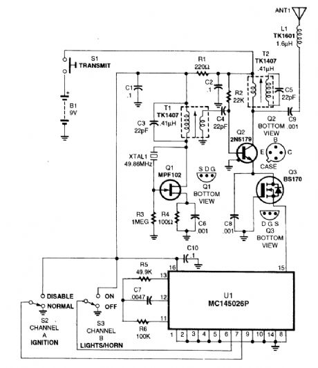
This transmitter operates at 49 MHz and uses an M145026 programmable digital encoder to generate a unique digital code, depending on the positions of S2 and S3, to control ignition and lights or horn. Q1 is the oscillator, Q2 the power amplifier. The antenna is a 36-inch whip or wire antenna. (View)
View full Circuit Diagram | Comments | Reading(2170)
| Pages:1425/2234 At 2014211422142314241425142614271428142914301431143214331434143514361437143814391440Under 20 |
Circuit Categories
power supply circuit
Amplifier Circuit
Basic Circuit
LED and Light Circuit
Sensor Circuit
Signal Processing
Electrical Equipment Circuit
Control Circuit
Remote Control Circuit
A/D-D/A Converter Circuit
Audio Circuit
Measuring and Test Circuit
Communication Circuit
Computer-Related Circuit
555 Circuit
Automotive Circuit
Repairing Circuit