
Circuit Diagram
Index 1431
CURRENT_TO_VOLTAGE_CONVERTER
Published:2009/6/17 4:30:00 Author:May
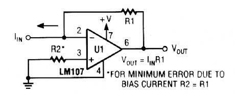
View full Circuit Diagram | Comments | Reading(5)
28_Vdc_TO_5_Vdc_CONVERTER
Published:2009/6/17 4:30:00 Author:May
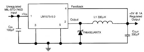
The National Semiconductor LM1575-5.0 allows a very simple switching regulator, with >80% ef-ficiency; operating as a 5-V source @ 1A from a +28-V bus. (View)
View full Circuit Diagram | Comments | Reading(1042)
ATV_DOWNCONVERTER
Published:2009/6/17 4:28:00 Author:May
This RF converts amateur TV signals in the 420- to 450-MHz region to VHF channel 3 or 4, allowing reception of those signals on a standard TV receiver. RF amplifier Q1 feeds mixer M1, and Q3 acts as an IF amplifier. Q2 is an oscillator operating around 378 MHZ and is tuneable over about a 30-MHz range. A complete kit is available from North Country Radio, P.O. Box 53, Wykagyl Station, NY 10804 (View)
View full Circuit Diagram | Comments | Reading(1216)
SINE_WAVE_TO_SQUARE_WAVE_CONVERTER
Published:2009/6/17 4:19:00 Author:May
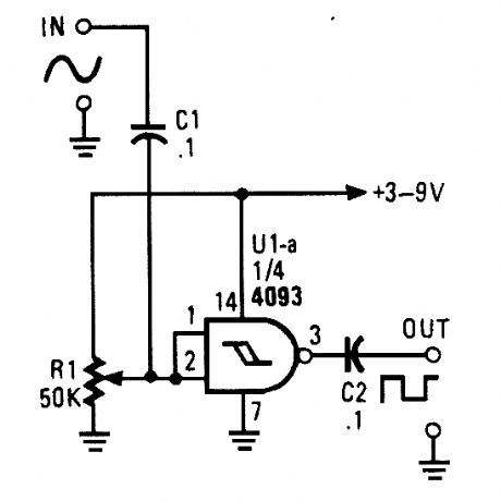
This circuit tums a sine wave into a square wave. It is comprised of a single 2-input NAND Schmitt trigger that's conftgured as an inverter with a trigger level adjustment at its input. As the input voltage rises above the gate's trigger point, the output snaps to its alternate state, producing a square-wave output. (View)
View full Circuit Diagram | Comments | Reading(2887)
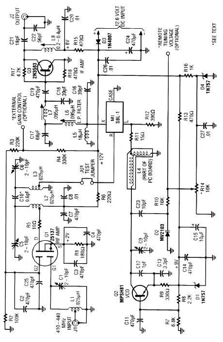
43925_MHz_ATV_DOWNCONVERTER
Published:2009/6/17 4:18:00 Author:May
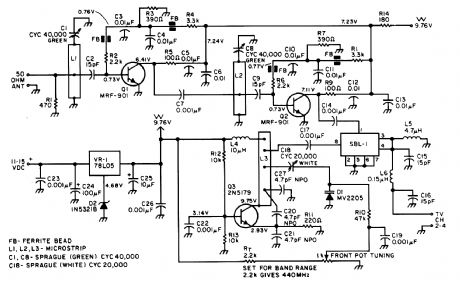
Most ATV (Amateur Television] transmitters transmit a DSB signal and commercial television stations use a VSB (Vestigial Sideband) signal. This fact is made use of in this converter to use the lower sideband. This results in less interference from repeaters that occupy the 440- to 445-MHz por-tion of the band. However, this approach might suffer from VHF image responses from channel 29, if that channel is active in your area. (View)
View full Circuit Diagram | Comments | Reading(886)
SINE_TO_SQUARE_WAVE_CONVERTER
Published:2009/6/17 4:15:00 Author:May
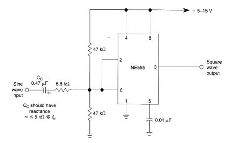
This 555-based Schmitt trigger circuit is useful for creating clock pulses from analog signals since it readily converts sine waves into square waves. (View)
View full Circuit Diagram | Comments | Reading(4507)
COMBUSTIBLE_GAS_DETECTOR
Published:2009/6/17 4:15:00 Author:May
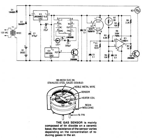
The circuit shown is useful for the detection of dangerous levels of combustible fumes or gases. It uses a comparator circuit to trigger an alarm buzzer. The sensor's resistant element is connected in series with resistor R1 to form a voltage-divider circuit; R1 is specifically matched to each gas sensor by the manufacturer. (View)
View full Circuit Diagram | Comments | Reading(3035)
SIMPLE_2_m-6_m_TRANSVERTER
Published:2009/6/17 4:14:00 Author:May

Using the bilateral properties of a balanced mixer this transverter will produce 6-m output with 2-m inputs. Y1 is a 90-MHz crystal. Note that the input on 2 m is 143 to 144 MHz for 53 to 54-MHz output. This avoids possibility of extraneous 2-m reception during receive periods. If your radio will not transmit below 144 MHz, then use a 93- or 94-MHz crystal frequency. (View)
View full Circuit Diagram | Comments | Reading(1633)
TEMPERATURE_TO_DIGITAL_CONVERTER
Published:2009/6/17 4:12:00 Author:May
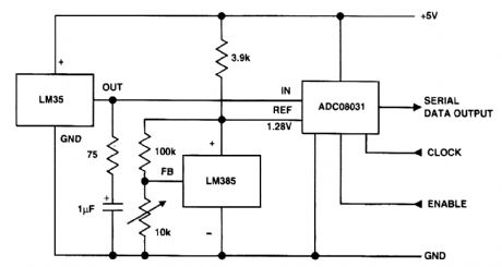
The devices shown from National Semiconductor are used in digital temperature circuit sensor LM35 and reference LM385 feed A-D converter ADC08031. (View)
View full Circuit Diagram | Comments | Reading(2755)
CRYSTAL_CONTROLLED_FREQUENCY_CONVERTER_USING_MOSFET
Published:2009/6/17 4:11:00 Author:May
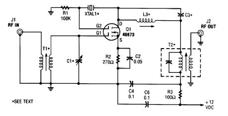
The second gate (G2) of a MOSFET can be used to incorporate a crystal oscillator into the same stage as a frequency mixer. Although old hat with tubes, this scheme is seldom seen in dual-gate MOSFET circuitry. L3, C3, and XI form the crystal oscillator, and T2 is an IF output transformer. T1 and C1 are tuned to the converter input frequency. This circuit should be useable up to 25 MHz or so, or higher with third-overtone crystals. (View)
View full Circuit Diagram | Comments | Reading(3133)
SIMPLE_CURVE_TRACER
Published:2009/6/17 4:10:00 Author:May
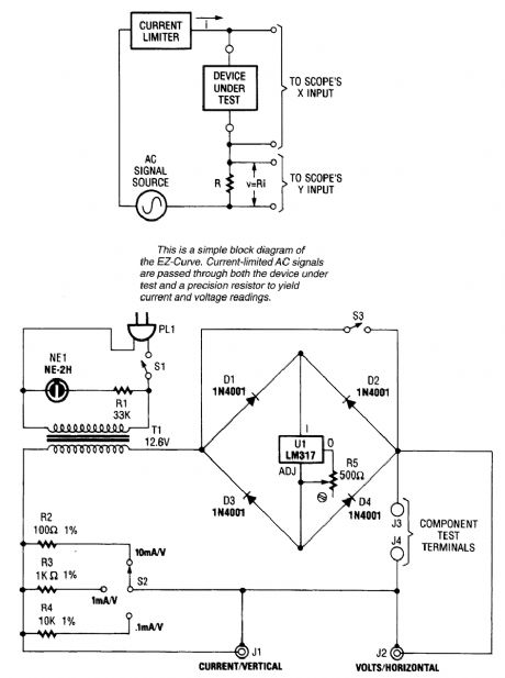
Useful for checking diodes, transistors, triacs, SCRs, resistors, and LEDs, this curve tracer should prove useful in the experimenter's lab. It displays the volt-ampere characteristic of a two-ter-minal device on an oscilloscope. (View)
View full Circuit Diagram | Comments | Reading(2657)
800_TO_1000_MHz_SCANNER_CONVERTER
Published:2009/6/17 4:09:00 Author:May
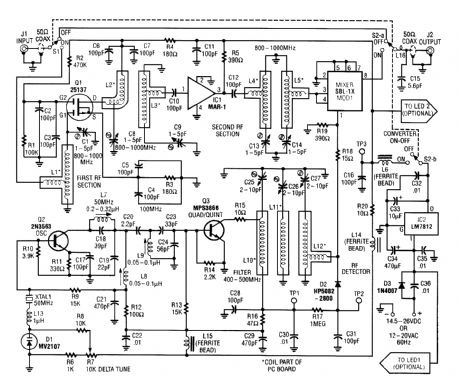
This converter enables reception of 800 to 1000 MHz on any scanner covering the 400 to 500-MHz range. The converter can be set up to cover either 800 to 900 MHz or by readjustment 900 to 1000 MHz. Sensitivity is very high because of the GASFET front end. For best results, the scanner should be of a programmable variety. A complete kit is available from North Country Radio, P.O. Box 53, Wykagyl Station, NY 10804. (View)
View full Circuit Diagram | Comments | Reading(1136)
CABLE_TESTER
Published:2009/6/17 4:09:00 Author:May
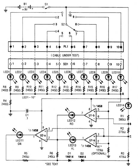
At the heart of the cable tester are two op amps, which are used as a window comparator to indicate a short- or open-circuit condition. A third op-amp comparator is used to indicate a good circuit (i.e., neither open nor shorted). Colored LEDs are used to show the condition of individual conductors within the cable under test; a red one to indicate a short between conductors, a yellow one to identify an open conductor, and a green one to signify that the conductor is okay. Individual LEDs of a bar-graph display are used to show which conductor in the cable is being tested. (View)
View full Circuit Diagram | Comments | Reading(3967)
RADAR_CALIBRATOR
Published:2009/6/17 4:07:00 Author:May
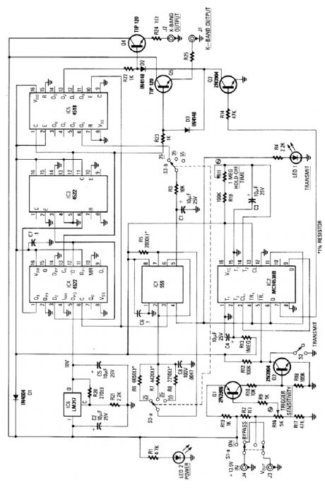
This circuit is basically a system that generates a pulsed modulation signal for a Gunn diode microwave oscillator. Several speed settings are preset (S3 a and b). A 555 timer is used with a frequency divider chain to produce Doppler shift equivalents of 25, 35, and 55 mph, for both X- and D-band radars. (View)
View full Circuit Diagram | Comments | Reading(1671)
VLF_CONVERTER
Published:2009/6/17 4:05:00 Author:May

This converter converts10 kHz to 150 kHz to 4.01 to 4.15 MHz for use with a shortwave receiver for VLF reception. A 4-MHz L.O. frequency is used. X1 can be a microprocessor XTAL or another suitable type. The antenna should be as long as possible. (View)
View full Circuit Diagram | Comments | Reading(1)
ELECTRONIC_SCALE
Published:2009/6/17 4:05:00 Author:May
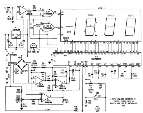
An electronic scale using a pressure transducer Goad cell) and an analog-digital (A/D) converter to drive a digital display is shown. The scale range depends on load cell. Display is calibrated in appropriate units. Components are on main circuit and display boards. The off-board controls are on the front panel and case. The cell in this scale is rated for 1.3 pounds (600 grams). (View)
View full Circuit Diagram | Comments | Reading(6447)
TEMPERATURE_TO_FREQUENCY_CONVERTER
Published:2009/6/17 4:03:00 Author:May
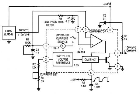
In this circuit an LM34 or LM35 produces a frequency proportional to temperature. Reference current (138 μA) is set via R3. The output can be used to drive a display, frequency counter, or other indicating device for temperature readout. (View)
View full Circuit Diagram | Comments | Reading(0)
DIGITAL_ALTIMETER
Published:2009/6/17 4:03:00 Author:May

A pressure sensor (IC4) is used with a dc amplifier to convert the bridge output (IC4) to a sin-gle-ended voltage. ICld provides a reference voltage for setting barometric pressure. IC3 is an A/D converter manufactured by Intersil. This drives an LCD module. Calibration reads out in fact. A vac-uum pump and a water-based manometer can be used for sensor calibration. (View)
View full Circuit Diagram | Comments | Reading(2239)
RC_DECADE_BOX
Published:2009/6/17 4:01:00 Author:May
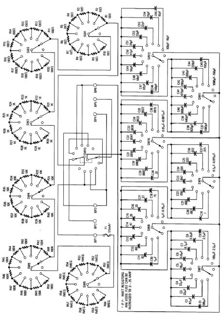
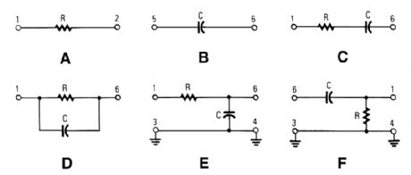
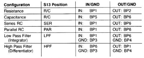
THE VARIOUS CONFIGURATIONS are set using S13: (a) resistor only and (b) capacitor only (both in position R/C); (c) series RC (position SER); (d) parallel RC (position PAR); (e) Low-Pass Filter (position LPF); and (f) High-Pass Filter (position HPF). The terminal numbers listed are those of bindinq-oosts BP1-BP6.
This decade box can be set for any resistance value between 10 Ω and 11.1 MΩ in 10-Ω stops. A switch can be used to configure several RC configurations. Use close tolerance components in the circuit. Ifpossible, check components with an accurate bridge or other means to ensure accuracy. (View)
View full Circuit Diagram | Comments | Reading(2946)
EXPLOSIVE_GAS_DETECTOR
Published:2009/6/17 4:00:00 Author:May
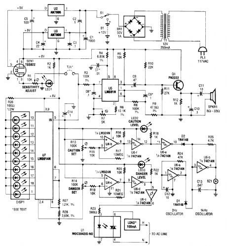
A gas sensor (TGS823 from Allegro Electronics, Cornwall Bridge, CT 06754) conducts in the presence of explosive gases. U5 is a voltage-to-frequency converter that produces a frequency proportional to the sensor conductance. The output frequency ranges from 100 Hz in clean air to 8 kHz in a contaminated atmosphere. The dc voltage from the sensor also drives bar graph LED U7 and comparators U4-b and U4-c to sense present caution and danger levels. U1 drives an ac load up to 100 mA (relay, indicator, alarm, etc.). (View)
View full Circuit Diagram | Comments | Reading(1985)
| Pages:1431/2234 At 2014211422142314241425142614271428142914301431143214331434143514361437143814391440Under 20 |
Circuit Categories
power supply circuit
Amplifier Circuit
Basic Circuit
LED and Light Circuit
Sensor Circuit
Signal Processing
Electrical Equipment Circuit
Control Circuit
Remote Control Circuit
A/D-D/A Converter Circuit
Audio Circuit
Measuring and Test Circuit
Communication Circuit
Computer-Related Circuit
555 Circuit
Automotive Circuit
Repairing Circuit