
Circuit Diagram
Index 1434
TRIANGLE_WAVE_OSCILLATOR
Published:2009/6/17 2:57:00 Author:May
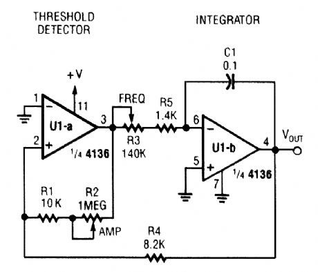
U1-b acts as an integrator while U1-a is a threshold detector. R2 sets the trip level and therefore the amplitude. R3 controls charging current of C1 and the frequency. (View)
View full Circuit Diagram | Comments | Reading(1711)
CAPACITANCE_MULTIPLIER
Published:2009/6/17 2:54:00 Author:May
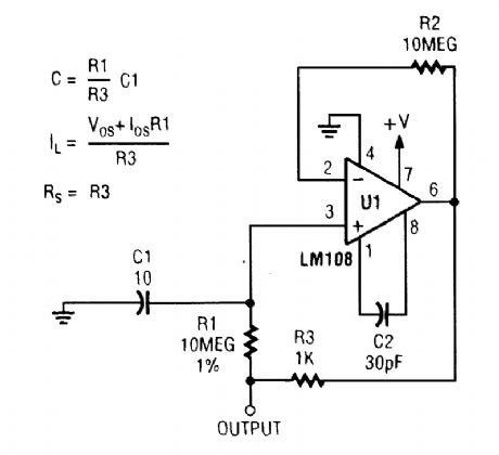
Capacitance multiplier uses the gain of an op amp to produce an effective capacitance-in this case 100,000 μF. (View)
View full Circuit Diagram | Comments | Reading(0)
SOLID_STATE_LIGHT_SOURCES_2
Published:2009/6/17 2:54:00 Author:May
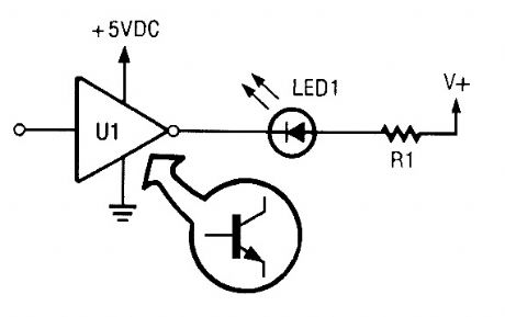
You can drive an LED with an open-collector TTL jnveder. The inveder shown must ground the LED to turn it on. (View)
View full Circuit Diagram | Comments | Reading(658)
SOLID_STATE_LIGHT_SOURCES_1
Published:2009/6/17 2:54:00 Author:May
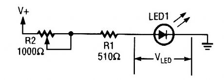
Since LED intensity is linearly related to the input current this circuit can be used to vary the LED s brightness via R2 (View)
View full Circuit Diagram | Comments | Reading(646)
SOLID_STATE_LIGHT_SOURCES
Published:2009/6/17 2:52:00 Author:May

In A we show two LED output curves derived by experiment. The circuit in B was used to get the data for the shod-circuit current plot, while the circuit in C yielded the data for the open-circuit voltage plot. (View)
View full Circuit Diagram | Comments | Reading(602)
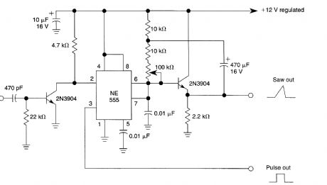
LINEAR_SAWTOOTH_GENERATOR
Published:2009/6/17 2:52:00 Author:May
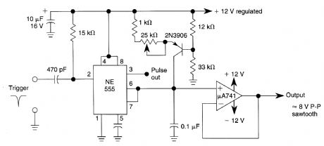
The 2N3906 transistor is used as a constant-current source, to assure that the 555-based sawLooth generator generates a linear ramp waveform. (View)
View full Circuit Diagram | Comments | Reading(2301)
TRANSISTORIZED_SCHMITT_TRIGGER
Published:2009/6/17 2:49:00 Author:May

View full Circuit Diagram | Comments | Reading(1186)
CODE_PRACTICE_OSCILLATOR
Published:2009/6/17 2:48:00 Author:May
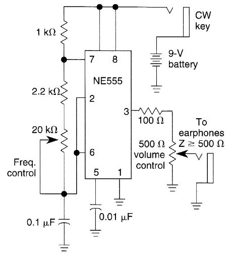
The tone and volume of the sound produced when the telegraph key is depressed can be varied in this code practice oscillator. (View)
View full Circuit Diagram | Comments | Reading(2)
BATTERY_OPERATED_BLACK_LIGHT
Published:2009/6/17 2:48:00 Author:May
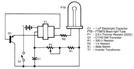
The battery-operated blagk light uses a “U”-shaped, unfiltered, black-light tube, which requires approximately 250 Vac to operate. To create the 250-Vac 6-V battery, the circuit uses a one-transis-tor blocking oscillator that drives a ferrite inverter transformer. A blocking oscillator tums itself off after one or more cycles. In this circuit, it consists of C1, P1, Q1, R1, and T1. The oscillations are sus-tained because the base of Q1 is connected to one of the windings on T1.Transformer T1 is a step-up transformer that consists of a ferrite core, which has a few tums on the primary and many turns on the secondary. The oscillating (ac) output of Q1 is fed to T1, which, because of its large tums ratio, converts the low-voltage signal into a high-voltage altemating cur-rent, which is coupled through resistor R2 to the black-light tube. Resistor R1 and trimmer resistor P1 limit the current flowing through the circuit. As the control on P1 is rotated, more current flows in the circuit, producing a brighter light output. (View)
View full Circuit Diagram | Comments | Reading(2288)
SIGNAL_GENERATOR
Published:2009/6/17 2:48:00 Author:May
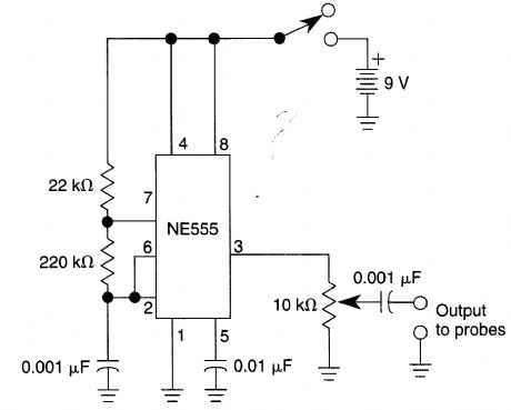
This simple oscillator is rich in harmonics which make this circuit useful for signal tracing applications. (View)
View full Circuit Diagram | Comments | Reading(144)
MORSE_PRACTICE_OSCILLATOR
Published:2009/6/17 2:47:00 Author:May
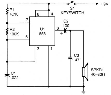
A 555 timer configured as an astable multivibrator is used in this circuit to generate an audio note. C1 can be changed to vary the audio note as desired. (View)
View full Circuit Diagram | Comments | Reading(1184)
TRIGGERED_SAWTOOTH_GENERATOR
Published:2009/6/17 2:46:00 Author:May
Two 2N3904 transistors and a 555 form a triggered sawtooth generator. A sawtooth or other rising voltage input provides a pulse output when the trigger point is reached. (View)
View full Circuit Diagram | Comments | Reading(1981)
QRP_SIDETONE_GENERATOR_CODE_PRACTICE_OSCILLATOR
Published:2009/6/17 2:44:00 Author:May
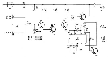
For use with low-power transmitters with a positive keying voltage. Q1/Q2/Q3 form a switching amplifier. When the key is pressed, the collector of Q3 goes to ground, tuming on Q5 and activating IC1, an audio oscillator. Q4 drives the speaker. For use as a code practice oscillator, insert P1 and J1 and a key in J2. (View)
View full Circuit Diagram | Comments | Reading(990)
555_BASED_RAMP_GENERATOR
Published:2009/6/17 2:43:00 Author:May
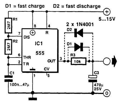
This circuit is used to generate a ramp voltage for tuning a radio receiver. An NE555, running at about 0.1 Hz, is used as an astable multivibrator. (View)
View full Circuit Diagram | Comments | Reading(2461)
DARK_ACTIVATED_RELAY
Published:2009/6/17 2:43:00 Author:May
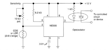
Configuring a 555 IC as shown yields a dark-activated relay with low hysteresis. CDS or LDR should be in the 2k to 8k range at desired light level. (View)
View full Circuit Diagram | Comments | Reading(1902)
PHOTOTRANSISTOR_CIRCUITS
Published:2009/6/17 2:43:00 Author:May
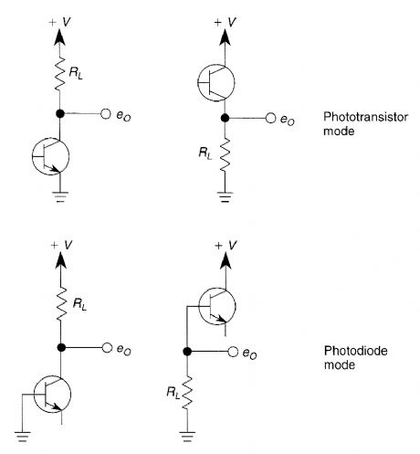
Here are four ways to connect a phototran-sistor for general use in phototransistor circuits. (View)
View full Circuit Diagram | Comments | Reading(1671)
LIGHT_CONTROLLED_OSCILLATOR
Published:2009/6/17 2:42:00 Author:May
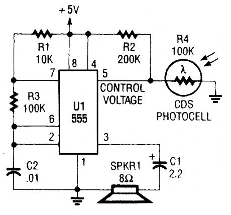
This circuit can be used as a light detector and possibly as an aid for the visually handi-capped. The frequency of the oscillator is deter-mined by the amount of illumination striking LDR4. (View)
View full Circuit Diagram | Comments | Reading(861)
SIMPLE_NONLATCHING_PHOTOCELL_SWITCH
Published:2009/6/17 2:41:00 Author:May
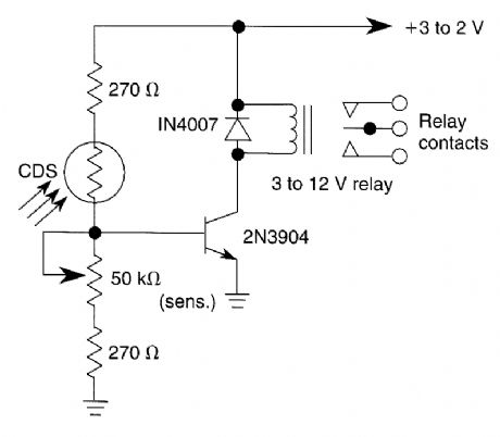
A CDS photocell is used to drive the relay.The circuit operates from a +12 V supply. (View)
View full Circuit Diagram | Comments | Reading(2301)
TRIANGLE_WAVE_GENERATOR
Published:2009/6/17 2:41:00 Author:May
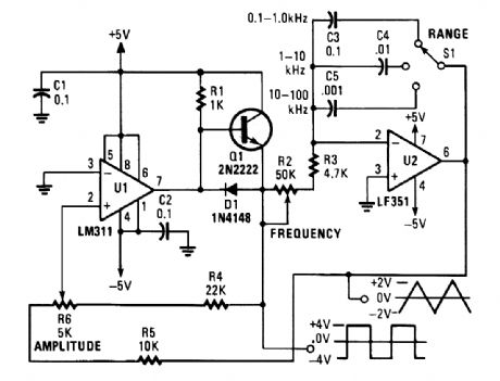
This is a simple triangle-wave generator using two IC devices and a transistor. The triangle wave is used as feedback to the square-wave generator. S1 allows range switching in three ranges from 100 Hz to 100 kHz. Extra positions could be used to extend the range to lower frequencies, using larger values of capacitance. (View)
View full Circuit Diagram | Comments | Reading(4116)
SELF_LATCHING_LIGHT_ACTIVATED_SWITCH
Published:2009/6/17 2:40:00 Author:May
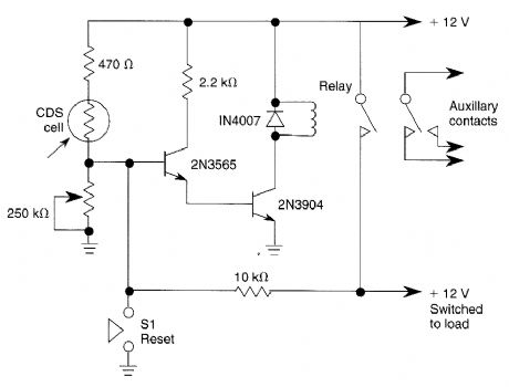
When light strikes the CDS cell it turns on the transistors which activates the relay which latches. Depressing 51 grounds the base of the 2N3565 and the relay resets. The 250 k potentiometer adjusts the sensitivity of the circuit. (View)
View full Circuit Diagram | Comments | Reading(1237)
| Pages:1434/2234 At 2014211422142314241425142614271428142914301431143214331434143514361437143814391440Under 20 |
Circuit Categories
power supply circuit
Amplifier Circuit
Basic Circuit
LED and Light Circuit
Sensor Circuit
Signal Processing
Electrical Equipment Circuit
Control Circuit
Remote Control Circuit
A/D-D/A Converter Circuit
Audio Circuit
Measuring and Test Circuit
Communication Circuit
Computer-Related Circuit
555 Circuit
Automotive Circuit
Repairing Circuit